
Automotive Electronics operate in environments that would destroy consumer-grade components. Temperature extremes, vibration, humidity, and the constant demand for zero defects over a 15-year lifespan require a fundamentally different approach to design and manufacturing. For Hdi Boards destined for automotive applications, meeting the AEC-Q100 qualification standard is not optional—it is the entry fee for working in this industry.
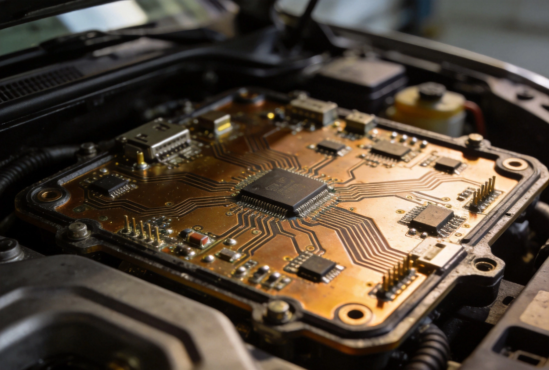
AEC-Q100 is the Automotive Electronics Council's stress test qualification for integrated circuits. While the standard is titled for ICs, it establishes the reliability expectations that flow through to the entire electronic assembly—including the PCB. The standard defines a battery of tests that simulate the environmental stresses a device will encounter over its lifetime in a vehicle.
The test categories include temperature cycling, high temperature operational life, humidity bias, moisture sensitivity level, ESD resistance, and mechanical stress tests like board flex and die attach shear. Each test specifies stress levels, sample sizes, and acceptance criteria. A component or assembly passes only if no failures occur during the stress test sequence.
For PCB designers, AEC-Q100 compliance means selecting materials, designing stack-ups, and specifying manufacturing processes that can survive these tests. The PCB itself is not AEC-Q100 qualified—it is the complete assembled unit—but the board must be capable of supporting components that undergo AEC-Q100 testing without failing.
Automotive environments push Pcb Materials to their limits. Under-hood applications see operating temperatures from -40°C to +150°C or higher. Even interior applications range from -40°C to +85°C or +125°C. These temperature swings, repeated thousands of times over the vehicle's life, create stress on the Pcb Materials, vias, and solder joints.
Standard FR-4 is rated for Tg (glass transition temperature) of around 130°C to 140°C. For high-temperature automotive applications, this margin is insufficient. High-Tg FR-4 materials with Tg above 150°C, or polyimide-based materials with Tg above 250°C, provide the thermal headroom needed for reliable operation. The material choice directly affects whether the board survives temperature cycling without delamination or via barrel cracking.
Humidity is another challenge. Moisture absorbed into the PCB can cause delamination during reflow soldering if the board is not properly baked before assembly. For automotive applications, materials with lower moisture absorption and strict process controls around board storage and handling are essential.
Hdi Boards present unique reliability challenges in automotive applications. The Microvia structures that provide routing density also introduce interfaces where failure can occur under thermal stress. The Sequential Lamination process that builds up HDI layers creates internal planes that must bond correctly to avoid delamination during temperature cycling.
Microvia Reliability is the primary concern. A Microvia that opens after temperature cycling is a field failure, not just a test failure. Automotive-qualified HDI requires process controls that ensure consistent via fill and plating, not just adequate electrical connectivity at room temperature. This means tighter process windows, more frequent in-process inspection, and potentially more conservative via aspect ratios than you would use in a consumer application.
The IPC-6012DA standard, specifically developed for automotive applications, defines minimum requirements for board construction including minimum plating thickness, registration tolerances, and defect acceptance criteria. HDI boards used in automotive must meet or exceed these construction requirements, which are more stringent than the general IPC-6012 specification.
Not all PCB materials are suitable for Automotive Hdi. The base material must have stable electrical properties across the operating temperature range, low moisture absorption, and consistent laser drillability for microvia formation.
Polyimide substrates offer the highest thermal capability and are the material of choice for the most demanding under-hood applications. They resist delamination at temperatures exceeding 250°C and maintain mechanical integrity through thousands of temperature cycles. The trade-off is cost and processing complexity—polyimide requires higher lamination temperatures and pressures, which increases manufacturing cost and requires equipment capable of the higher process temperatures.
High-Tg FR-4 with modified epoxy systems provides adequate Thermal Performance for many automotive interior applications at lower cost than polyimide. These materials handle temperature cycling well when properly processed, and their processing characteristics are closer to standard FR-4, making them more accessible to a wider range of manufacturers.
For HDI specifically, the core and prepreg materials must be compatible with Laser Drilling. Some materials form inconsistent via walls or leave carbon residue after desmear, which interferes with reliable plating. Your fabricator's material specifications should include laser drill compatibility data.
The HDI stack-up must be designed with automotive stress in mind. Symmetrical stack-ups resist warpage better than asymmetrical designs, which matters for boards that undergo thermal cycling. Balanced construction—equal copper weights and material thicknesses on opposing layers—reduces the internal stress that can cause delamination or warpage.
For boards with components on both sides, the assembly thermal profile must be considered in the Stack-up Design. Lead-free reflow profiles reach peak temperatures of 260°C or higher, which can cause stress in thick boards with high thermal mass. Thinner boards with lower thermal mass heat more uniformly, reducing the thermal gradients that cause warpage and delamination.
Via-in-pad structures, while enabling denser routing, introduce reliability risk in automotive applications because the plated via fills can crack under thermal cycling if not properly processed. Many automotive OEMs restrict or prohibit Via-in-pad on safety-critical boards. Verify your customer's requirements before committing to via-in-pad in an automotive design.
Automotive quality requires process controls that go beyond standard commercial Pcb Manufacturing. The IATF 16949 automotive Quality Management System defines the framework—statistical process control, lot traceability, incoming material verification, and rigorous change control—but the execution is what matters.
Plating thickness control is critical. The current density, bath chemistry, and plating time must be maintained within tight ranges to achieve consistent via barrel plating. For Automotive Hdi, minimum plating thickness requirements are typically 25 microns or higher for through-hole vias, with microvia plating requirements specified by the fabricator based on their process capability.
Visual inspection criteria are stricter. IPC Class 3 (high-reliability) acceptance criteria are the baseline, but automotive customers often impose additional requirements for specific defect types. Minimum Annular Ring width, maximum void content in plated vias, and registration tolerances are all specified more tightly than for commercial boards.
Lot traceability must extend from the raw laminate through every manufacturing step to the finished board. If a field failure occurs, the manufacturer must be able to identify the production lot of the affected board and trace back through the manufacturing records to identify any process anomalies that might explain the failure.
Designing for automotive HDI reliability starts in the schematic and layout phase. Component placement should minimize thermal gradients across the board during assembly. High-power components that generate heat should be positioned away from the board center where thermal mass creates temperature gradients during reflow.
Vias should be placed away from board edges and panel depaneling features. The stress concentrations introduced by depaneling can propagate into nearby vias and cause failures during subsequent thermal cycling. Maintain minimum distances from board edges and panel routing channels.
Thermal relief design affects solder joint reliability. Components that will be wave soldered or hand-soldered during field repair require thermal reliefs that allow heat to flow away from the pad during soldering. Components that will only go through reflow assembly can use solid connections to the plane for better Thermal Conductivity.
The DFM review for automotive boards should include a Thermal Simulation to identify hot spots and temperature gradients during assembly. This simulation, combined with material selection and Stack-up Design, identifies potential reliability risks before the board goes to production.
Automotive HDI boards must undergo qualification testing before they can be used in production. The qualification sequence typically includes thermal cycling, temperature humidity bias, highly accelerated stress testing (HAST), board flex testing, and visual/mechanical inspection. The specific tests and stress levels depend on the application—under-hood applications require more severe testing than interior applications.
The qualification sample size must be statistically significant. AEC-Q100 specifies minimum sample sizes based on the total number of devices in the family being qualified. For PCB qualification, a common approach is to test 30 boards per stress condition with zero failures allowed.
Failure analysis is required for any test failure. A single failed via or delaminated layer must be root-caused and the manufacturing process corrected before retesting. This requirement drives continuous improvement in process capability and quality systems.
Not all PCB manufacturers are capable of producing automotive-qualified HDI. The combination of HDI complexity, automotive material requirements, and IATF 16949 quality systems limits the supplier base. Plan for a longer qualification cycle than you might expect—typically 6–12 months from initial engagement to approved supplier status.
Verify your chosen manufacturer's automotive experience directly. Ask for references in your application area, review their quality manuals and process capabilities, and consider a plant audit before committing to production volumes. The investment in supplier qualification upfront prevents costly field failures and supply disruptions later.
The automotive HDI supply chain is demanding, but it is also more stable than commercial electronics. Automotive programs run for 5–10 years with consistent volumes, providing long-term stability that benefits both buyer and supplier. If your application fits automotive requirements, the investment in qualification is worth it.

HDI Solutions for In-Vehicle Infotainment (IVI) and ClustersAugust/07/2026
Designing Automotive HDI Boards for Vibration and Shock ResistanceJuly/17/2026
How HDI Technology Supports Advanced Driver Assistance Systems (ADAS)June/25/2026

The Role of HDI in Avionics and Flight Control SystemsAugust/13/2026
Understanding the Core Differences Between HDI and Traditional PCBsJuly/02/2026
The Role of HDI in Robotics and Motion Control SystemsAugust/10/2026
The Impact of Plating Voids on HDI Interconnect ReliabilityJuly/10/2026

An Introduction to ABF (Ajinomoto Build-up Film) for Advanced HDIJuly/27/2026