
High-density Interconnect (HDI) technology has revolutionized electronics by enabling Miniaturization while maintaining or increasing functionality. However, as power densities increase and board real estate shrinks, Thermal Management becomes one of the most critical challenges facing designers of high-power Hdi Applications. Heat affects everything from component reliability to system efficiency, with excessive temperatures reducing component lifespan, degrading performance, and potentially causing catastrophic failure. Managing heat effectively requires understanding the fundamental mechanisms of heat generation, transfer, and dissipation in HDI structures. This practical guide provides designers and engineers with actionable strategies for Thermal Management in high-power Hdi Applications, bridging the gap between theoretical principles and practical implementation.
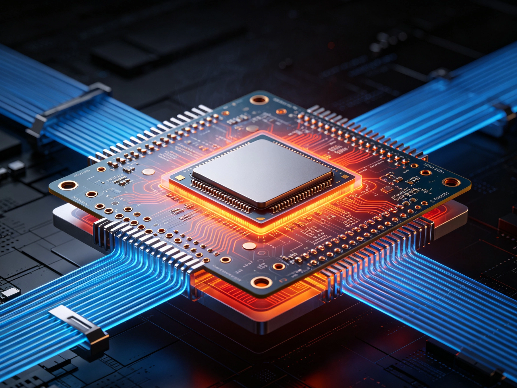
Hdi Technology creates unique thermal challenges that differ significantly from Traditional Pcb designs. The high component density in Hdi Boards means heat-generating components are placed closer together, creating thermal coupling effects where adjacent components heat each other. Microvia structures, while enabling Miniaturization, create thermal conduction paths that concentrate heat in specific areas. The thin dielectrics used in HDI constructions often have lower Thermal Conductivity than traditional substrates, creating thermal resistance that impedes heat spreading. Layer count increases in HDI designs complicate thermal paths, as heat must travel through multiple dielectric layers to reach heat sinks or Thermal Vias. Component miniaturization reduces the surface area available for Heat Dissipation while power consumption remains constant or increases. Ball grid array (BGA) and chip-scale packaging (CSP) techniques used in HDI limit the thermal contact area between components and boards, impeding heat transfer from packages to substrates. The cumulative effect of these factors means thermal issues in HDI designs are more likely to occur and more difficult to address than in Traditional Pcb designs.
Understanding where heat originates enables targeted thermal management strategies. Active semiconductor devices including processors, FPGAs, and power transistors generate the majority of heat through switching losses and conduction losses during operation. Voltage drop across PCB traces carrying high currents creates resistive heating proportional to current squared times resistance. Power supply components including inductors, MOSFETs, and regulators convert electrical energy to heat during voltage conversion and regulation. LED drivers and lighting circuits dissipate significant power, particularly in high-brightness applications. RF power amplifiers in communication systems generate substantial heat during signal amplification. Motor drivers and motor control circuits dissipate heat proportional to load current and switching frequency. Battery charging circuits generate heat during fast charging operations. Thermal design must account for all significant heat sources and their contributions to total thermal load, enabling appropriate thermal management strategies for each source type.
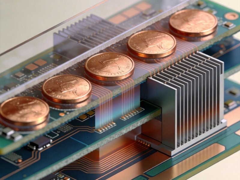
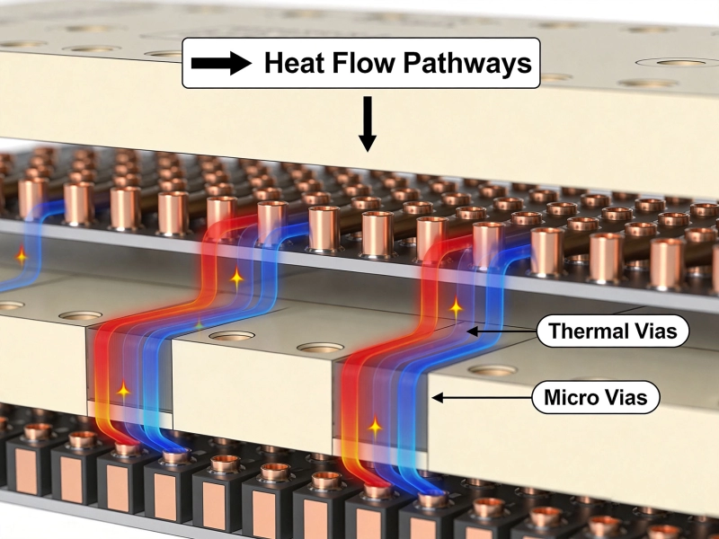
Thermal conduction represents the primary mechanism for moving heat from components to heat sinks or ambient air in HDI designs. Copper planes in multilayer Hdi Boards provide excellent Thermal Conductivity, spreading heat across board surfaces and enabling heat transfer to mounting hardware and enclosures. Thermal Vias create vertical conduction paths through board layers, enabling heat from components on surface layers to reach internal planes or bottom-side heat sinks. Thermal interface materials including thermal pads, thermal paste, and phase change materials fill microscopic air gaps between components and heat sinks, improving thermal contact. Component packages including thermal pads, exposed pads, and metal bottoms provide direct thermal connection points for heat extraction. PCB substrate materials have relatively low thermal conductivity compared to copper, creating thermal resistance that limits heat spreading through the board itself. Strategic component placement can optimize thermal conduction by positioning heat-generating components over or near thermal planes, vias, and heat sinks.
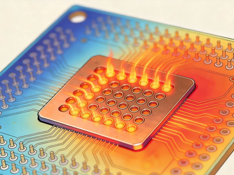
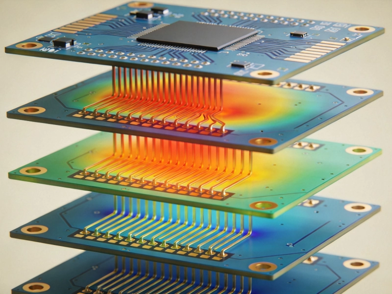
Thermal vias represent one of the most effective and practical methods for heat management in HDI boards. Thermal vias provide vertical conduction paths through the board thickness, enabling heat to flow from component attachment surfaces to internal planes, bottom-side heat sinks, or external thermal management structures. Via array density significantly impacts Thermal Performance, with more closely spaced vias providing lower thermal resistance. Via geometry including diameter, spacing, and plating thickness influences thermal resistance and manufacturing cost. Microvias in HDI designs can serve dual purposes, providing both electrical connections and thermal conduction paths. Filled thermal vias offer improved thermal transfer compared to unfilled vias, though at increased cost. Solder mask coverage over thermal vias can reduce thermal transfer efficiency and should be considered during design. Thermal via placement should align with component thermal pads and extend to ground planes or thermal interface surfaces. Optimization of thermal via designs requires balancing Thermal Performance against manufacturing cost and board space constraints.
Heat sinks provide the primary mechanism for dissipating heat from HDI boards to ambient air. Heat sink selection involves matching thermal resistance to component power dissipation while considering size, cost, and attachment constraints. Forced air cooling using fans dramatically improves heat sink effectiveness compared to natural convection, with airflow rate and direction significantly impacting cooling performance. Heat sink attachment methods including mechanical clips, adhesive bonding, and solder attachment each offer different trade-offs in thermal resistance, reliability, and serviceability. Thermal interface materials between heat sinks and components or boards fill microscopic gaps and improve thermal contact. Spreading heat across larger heat sink surfaces reduces temperature rise for given power dissipation. Heat pipes and vapor chambers provide highly effective thermal transfer for applications where conventional heat sinks cannot reach all heat sources. Integration of heat sinks into product enclosures can reduce external heat sink size while meeting thermal requirements.
PCB layout significantly impacts thermal performance in high-power HDI applications. Power traces carrying high currents should be wide and short to minimize resistive heating, with copper weight increasing for high-current paths. Placement of heat-generating components should consider thermal coupling effects, avoiding clustering of high-power devices that would compound heating. Ground and power planes provide thermal spreading that reduces hot spot temperatures and provides thermal mass that absorbs transient thermal loads. Signal routing should avoid crossing thermal paths and creating thermal gradients that could affect sensitive circuits. Thermal isolation of temperature-sensitive circuits from heat-generating components prevents performance degradation. Split planes can isolate noisy digital circuits from sensitive analog circuits while maintaining thermal connectivity where beneficial. Component orientation can optimize airflow patterns when forced air cooling is used. Thermal Simulation during layout enables optimization before fabrication, avoiding thermal problems that would require expensive redesigns.
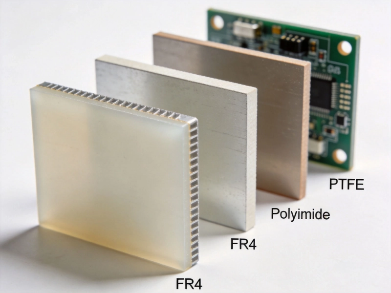
Material selection profoundly impacts thermal performance in HDI designs. Standard FR-4 substrates have thermal conductivity around 0.3 W/mK, creating significant thermal resistance in thick sections. High-Tg FR-4 materials offer improved thermal stability but similar thermal conductivity to standard FR-4. Polyimide substrates provide better thermal stability and slightly improved thermal conductivity. Metal-core substrates including aluminum and copper base materials offer thermal conductivity exceeding 150 W/mK, dramatically improving heat spreading. IMS (insulated metal substrate) constructions provide electrical isolation while enabling effective thermal conduction to metal cores. Ceramic substrates including alumina and aluminum nitride offer high thermal conductivity and excellent electrical isolation. Thermal prepregs with enhanced thermal conductivity are available for multilayer constructions requiring improved thermal paths. Thermal interface materials range from thermal tapes at 0.5-2 W/mK to thermal greases exceeding 10 W/mK, enabling optimization of interface thermal resistance.
Active cooling solutions provide enhanced thermal management beyond passive approaches for demanding HDI applications. Fans provide forced air circulation that dramatically improves convective heat transfer compared to natural convection. Fan selection considers airflow volume, static pressure capability, acoustic noise, power consumption, and reliability. Liquid cooling systems using microchannels or heat exchangers provide highly effective cooling for extreme power densities. Thermoelectric coolers (TECs) can provide precise temperature control for applications requiring tight thermal regulation. Evaporative cooling techniques offer high Heat Dissipation capacity for specialized applications. Active cooling solutions require power, controls, and often additional reliability engineering, adding complexity and cost. Thermal management integrated circuits provide closed-loop control of cooling systems including fan speed regulation and temperature monitoring. Redundant cooling designs may be required for critical applications where cooling failure could cause system failure.
Thermal Simulation enables designers to predict thermal performance and optimize designs before fabrication. Computational fluid dynamics (CFD) analysis simulates heat transfer and fluid flow, predicting temperature distributions and identifying hot spots. Finite element analysis (FEA) provides detailed thermal-stress coupling for evaluating mechanical reliability under thermal loads. Steady-state thermal analysis determines maximum operating temperatures under continuous power conditions. Transient thermal analysis evaluates thermal response to power cycling and transient loads. Component placement optimization using simulation tools can reduce peak temperatures by 15-30% compared to initial layouts. Sensitivity analysis identifies which thermal parameters most significantly impact performance, guiding optimization efforts. Simulation validation through physical testing ensures correlation between predicted and actual thermal behavior. Iterative simulation-design cycles progressively optimize thermal performance throughout the development process.
Physical measurement validates thermal design and identifies issues not captured by simulation. Infrared thermography provides non-contact temperature mapping across board surfaces, identifying hot spots and thermal gradients. thermocouple attachment enables precise temperature measurement at specific locations including component junctions. Thermal test vehicles with embedded sensors provide detailed thermal mapping and validation of simulation models. Power cycling tests evaluate thermal fatigue and reliability under representative operating conditions. Thermal resistance measurement from junction to case, case to heat sink, and heat sink to ambient enables validation of thermal paths. Environmental testing at temperature extremes verifies thermal management effectiveness across operating ranges. Long-term reliability testing under thermal stress identifies failure mechanisms related to thermal management. Measurement data feeds back into simulation correlation, improving model accuracy for future designs.
Thermal management directly impacts product reliability through multiple mechanisms. Junction temperature strongly influences semiconductor failure rates, with reliability typically doubling for every 10°C reduction in operating temperature. Thermal cycling causes fatigue in solder joints, vias, and component attachments, potentially causing cracking and open circuits. Coefficient of thermal expansion (CTE) mismatches between materials create stress during temperature changes, particularly at component-to-board interfaces. Long-term exposure to elevated temperatures accelerates aging of polymers including substrates, conformal coatings, and encapsulants. Electrochemical migration and dendrite growth rates increase at elevated temperatures, potentially causing short circuit failures. Derating guidelines from component manufacturers specify maximum temperatures and power levels for reliable operation. Lifetime predictions based on Arrhenius models relate operating temperature to expected failure rates. Thermal management strategies should consider both steady-state thermal performance and thermal cycling durability.
Successful thermal management in high-power HDI applications requires systematic attention throughout the design process. Early thermal analysis during concept development identifies potential thermal issues before major design commitments. Component selection should consider power dissipation, thermal resistance, and maximum ratings alongside functional requirements. Board stackup design should include thermal planes and appropriate layer allocation for heat spreading. Thermal via placement should align with component thermal connections and extend to thermal sinks. Heat sink selection and attachment design should consider thermal resistance, mechanical constraints, and manufacturing processes. Layout Optimization should position components for thermal efficiency while maintaining Signal Integrity. Simulation should validate thermal performance before fabrication. Testing should verify thermal performance meets requirements under all operating conditions. Documentation should capture thermal design rationale, analysis results, and test data for future reference and Troubleshooting.
Managing heat in high-power HDI applications requires systematic attention to thermal design from concept through production. The unique challenges of Hdi Technology—high component density, thin dielectrics, complex layer structures—demand thoughtful thermal management that integrates with electrical and mechanical design. This practical guide has provided strategies for understanding thermal challenges, implementing effective thermal management, and validating thermal designs. Success requires balancing thermal performance against cost, size, and manufacturing constraints while meeting reliability requirements for the intended application. As power densities continue increasing in HDI applications, thermal management skills become increasingly valuable for engineers working on advanced electronics. Investment in thermal management capability—in terms of tools, knowledge, and design practices—pays dividends through improved product reliability, reduced development time, and successful project outcomes. The principles and practices outlined in this guide provide a foundation for effective thermal management in demanding HDI applications.
What are the most effective thermal management techniques for HDI boards?
The most effective thermal management techniques for HDI boards include thermal vias connecting components to internal or bottom-side heat sinks, copper plane spreading for heat distribution, metal-core substrates for high thermal conductivity, strategic component placement avoiding thermal coupling, and proper heat sink integration with appropriate thermal interface materials. For extreme power densities, active cooling including forced air or liquid cooling may be necessary. The optimal approach depends on power levels, size constraints, and cost targets.
How do thermal vias improve heat dissipation?
Thermal vias provide vertical conduction paths through the PCB thickness, enabling heat to flow from surface-mounted components to internal planes, bottom-side heat sinks, or mounting surfaces. Via arrays with close spacing provide lower thermal resistance than sparse arrays. Filled thermal vias offer improved thermal transfer compared to unfilled vias. Thermal via placement should align with component thermal pads and extend to ground planes or thermal interface surfaces for maximum effectiveness.
What impact does material selection have on thermal performance?
Material selection significantly impacts thermal performance because substrate thermal conductivity determines heat spreading capability through the board. Standard FR-4 has thermal conductivity around 0.3 W/mK, while metal-core substrates exceed 150 W/mK. Higher thermal conductivity materials enable more effective heat spreading but often at higher cost. For high-power HDI applications, selecting materials with appropriate thermal conductivity and thermal stability is essential for meeting thermal requirements.
When should active cooling be considered for HDI applications?
Active cooling should be considered when passive thermal management cannot maintain component temperatures within ratings, when power densities exceed approximately 0.5-1 W/cm2, when ambient temperatures approach maximum operating limits, when product size constraints limit heat sink dimensions, or when tight temperature control is required for performance or reliability. Active cooling solutions including fans, liquid cooling, and thermoelectric coolers provide enhanced thermal management at the cost of increased complexity, power consumption, and potential reliability concerns.
How does thermal simulation help in HDI design?
Thermal simulation enables designers to predict temperature distributions, identify hot spots, and optimize thermal management before fabrication. Cfd Analysis simulates heat transfer and fluid flow, while FEA provides detailed thermal-stress coupling. Simulation reduces development time by identifying issues early when changes are inexpensive, enables optimization of thermal designs that would be impractical through trial-and-error, and provides quantitative data for design decisions. Correlation with physical testing improves simulation accuracy over time.
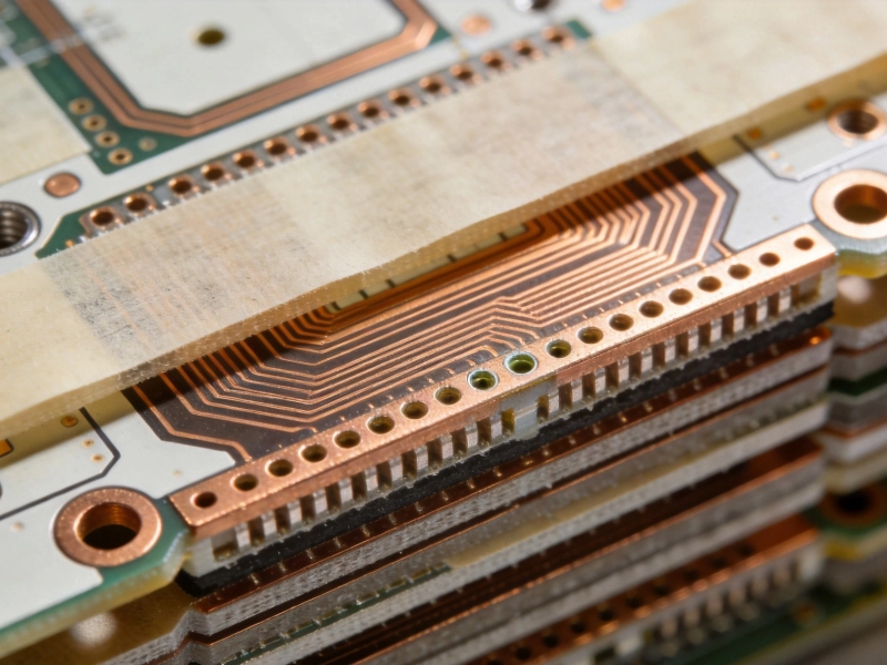
Exploring the 6 Types of HDI Structures: From Type I to Any-LayerAugust/14/2026
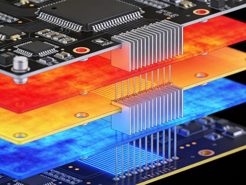
Effective Thermal Management Strategies for High-Density PCBsMay/28/2026
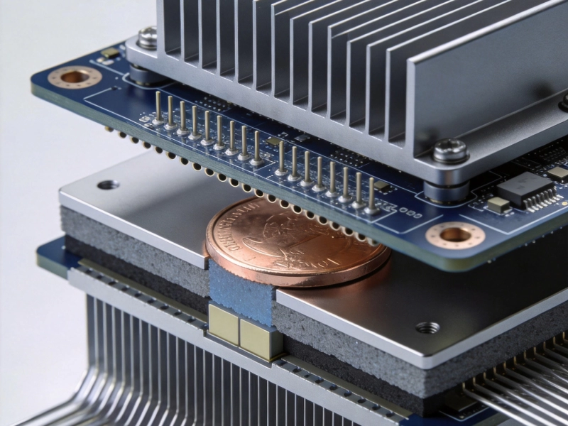
Thermal Management Strategies for HDI Power ModulesSeptember/11/2026
Selecting the Right Dielectric Materials for High-Performance HDI PCBsMay/28/2026
The Impact of Via-in-Pad on Thermal Performance and ReliabilitySeptember/26/2026
Copper Coin and Embedded Heat Sinks: Advanced Cooling for HDIJuly/08/2026
The Role of Thermal Vias in Dissipating Heat from HDI BoardsJune/09/2026
How to Use Thermal Simulation Software to Optimize HDI LayoutsJuly/29/2026