Open Nav

High-density Interconnect (HDI) technology has revolutionized modern electronics, allowing for smaller form factors and higher functionality in devices ranging from smartphones to aerospace avionics. However, as trace widths shrink and signal frequencies rise into the gigahertz range, the choice of dielectric material becomes the single most critical factor in ensuring board reliability and performance.
In this article, we will explore the key parameters engineers must consider when selecting dielectrics for high-performance Hdi Applications.
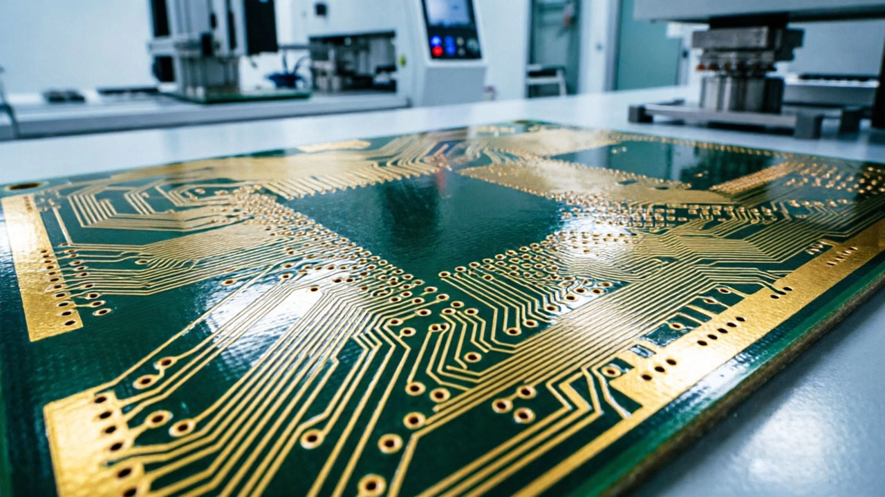
The Dielectric Constant (Dk), also known as relative permittivity, determines the speed at which an electrical signal travels through the material. In high-speed digital designs, Signal Integrity is paramount.
While Dk affects speed, the Dissipation Factor (Df), or loss tangent, affects signal strength. As signals travel through the PCB traces, energy is lost to the dielectric material as heat.
For high-performance Hdi Boards operating at 5G or mmWave frequencies, standard FR-4 materials often exhibit too much signal loss. Engineers typically turn to specialized laminates such as Polyphenylene Oxide (PPO) or Polytetrafluoroethylene (PTFE) based materials, which offer ultra-low Df values to preserve Signal Integrity over longer distances.
Hdi Boards are densely packed, leading to significant heat generation. The dielectric material must withstand these thermal stresses without degrading.
Coefficient of Thermal Expansion (CTE): It is vital to match the CTE of the dielectric material with that of the copper traces and the components. A mismatch can cause mechanical stress during thermal cycling, leading to via cracking or delamination—common failure modes in HDI structures.
Glass Transition Temperature (Tg): For lead-free assembly processes which require higher reflow temperatures, high-Tg materials are mandatory to prevent the board from softening and warping.
Not all high-performance materials are created equal when it comes to manufacturability. HDI fabrication involves complex processes like Laser Drilling for Microvias and Sequential Lamination.
Some advanced Low-loss Materials can be difficult to drill or may have poor adhesion between layers. Selecting a material that balances electrical performance with processability is key to avoiding yield issues and keeping production costs manageable.
Choosing the right dielectric for an Hdi Pcb is a balancing act between electrical performance, thermal reliability, and cost. By carefully evaluating Dk, Df, and thermal properties against your specific application requirements, you can ensure your design meets the rigorous demands of today's high-tech landscape.
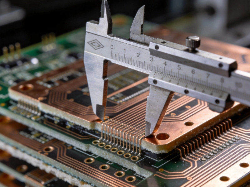
Managing Layer-to-Layer Registration Accuracy in Multilayer HDIOctober/09/2026
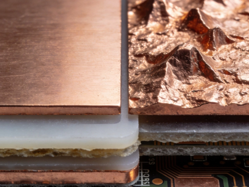
Understanding the Role of Copper Foil Roughness in Signal IntegritySeptember/23/2026
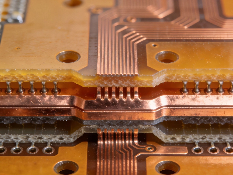
FR-4 vs. High-Tg Materials: What Works Best for HDI Applications?July/07/2026
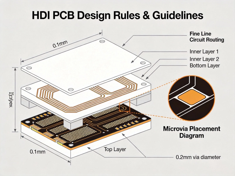
Essential HDI PCB Design Rules for Beginners and ExpertsMay/28/2026
An Introduction to ABF (Ajinomoto Build-up Film) for Advanced HDIJuly/27/2026
Why Low Loss Materials are Critical for High-Speed HDI DesignsSeptember/01/2026
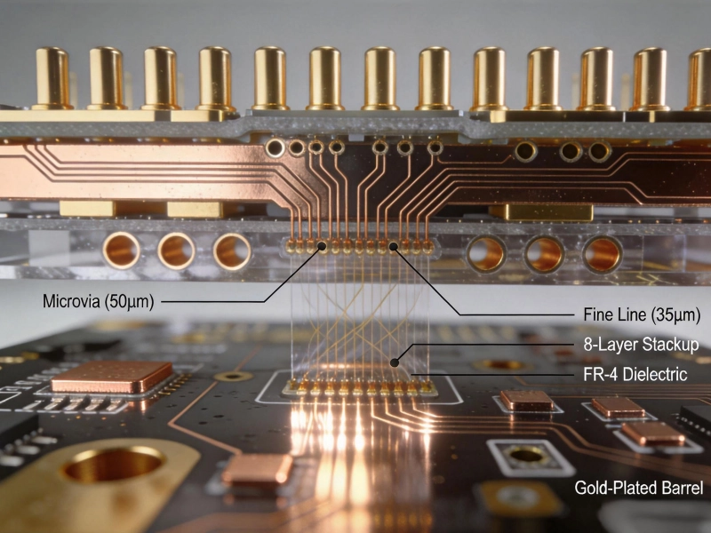
What is High Density Interconnect (HDI) PCB?May/28/2026
HDI PCB Cost Guide: What Factors Drive the Price Up?June/16/2026