Open Nav

High-density Interconnect (HDI) printed circuit boards sit at the heart of virtually every smartphone, tablet, and advanced medical device produced today. The technology enables Miniaturization at a scale that would have seemed impossible two decades ago—hundreds of components packed into spaces measured in square centimeters, connected through Microvia structures with diameters smaller than a human hair. What often goes unappreciated is the critical role that substrate material choice plays in making HDI possible.
Among the various material options available to PCB designers and fabricators, FR-4 and high-Tg materials represent the two poles of a decision that carries significant implications for Thermal Performance, mechanical reliability, manufacturing complexity, and cost. Understanding the characteristics of each—and knowing when each material shines—separates successful HDI implementations from those that fail mysteriously in the field.
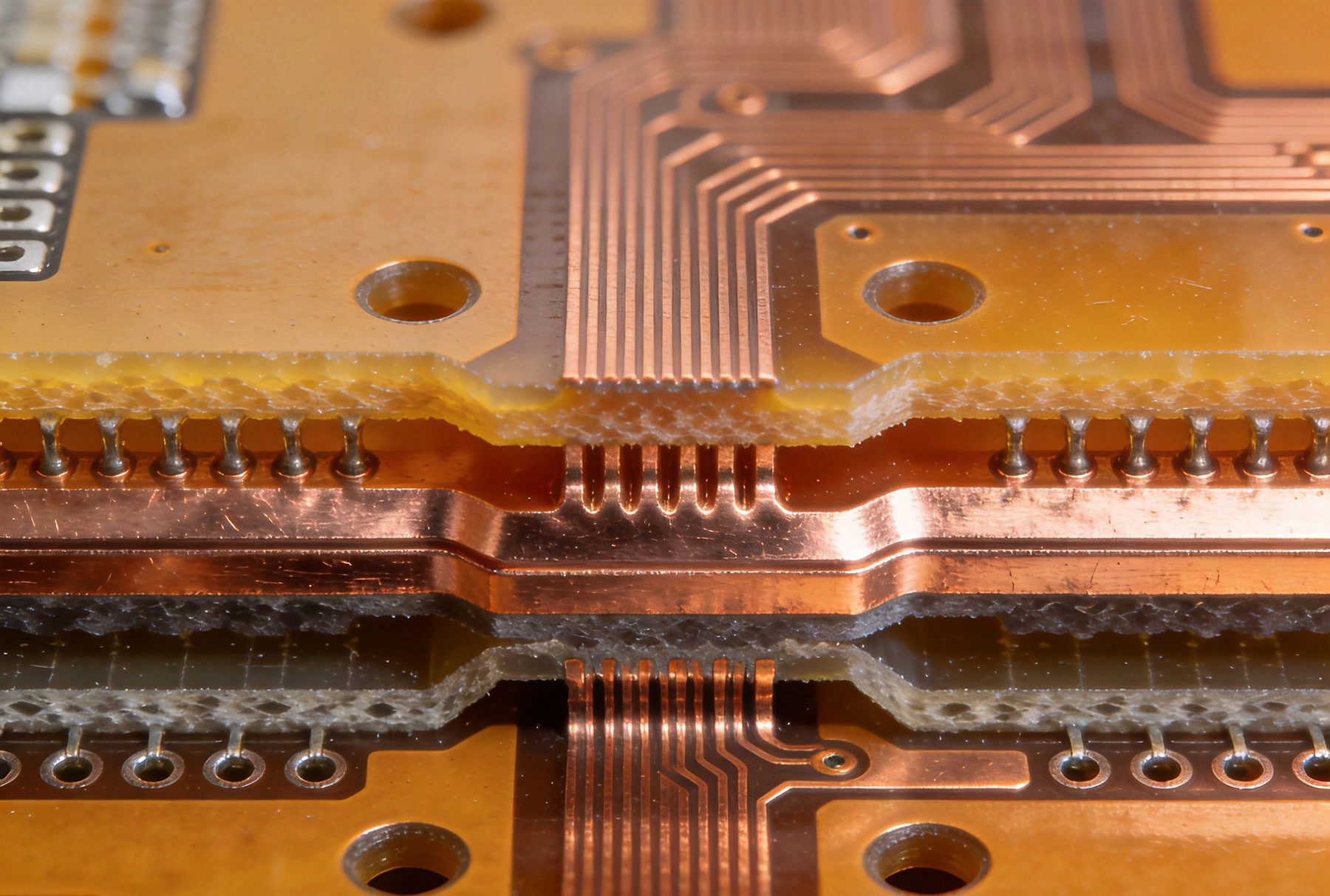
Before comparing FR-4 and high-Tg materials, we need to understand what Tg actually represents and why it matters for Hdi Applications.
The glass transition temperature (Tg) marks the point at which a polymer material transitions from a rigid, glassy state to a softer, rubbery state. Below Tg, the material maintains its molecular structure with minimal flexibility. Above Tg, the polymer chains gain mobility, causing the material to soften and its mechanical properties to change significantly.
For PCB substrates, this transition has profound consequences. A board designed to operate at 125°C with a Tg of 135°C has almost no margin. Even brief thermal excursions—during assembly reflow, from ambient temperature spikes, or from component self-heating—can push the material above Tg, causing dimensional instability, pad shift, and interconnection failures.
Standard FR-4 materials typically exhibit Tg values between 125°C and 140°C. High-Tg materials, as the name suggests, push this threshold significantly higher—typically between 150°C and 180°C, with some specialty formulations exceeding 200°C. This elevated thermal margin translates directly to improved reliability in demanding applications.
FR-4—an epoxy resin reinforced with woven glass fabric—has served as the dominant PCB substrate since the 1950s. Its success stems from an attractive combination of properties: reasonable Thermal Performance, excellent electrical insulation, good mechanical strength, and crucially, relatively low cost. FR-4 manufacturing processes are mature, well-understood, and supported by an enormous supply chain.
For standard multilayer boards and many consumer electronics applications, FR-4 remains entirely appropriate. The material handles typical lead-free assembly reflow profiles (peak temperatures of 245°C to 260°C) without catastrophic failure, provided thermal margins are properly accounted for in design. Most HDI consumer products—smartphones, tablets, and wearable devices—use FR-4 or modified FR-4 formulations in many board layers.
However, FR-4 carries limitations that constrain its suitability for demanding Hdi Applications. Thermal performance below Tg, while adequate for consumer products, may prove insufficient for boards that must survive multiple assembly cycles, high ambient temperatures, or significant power dissipation. The material's relatively high moisture absorption—typically 0.10% to 0.15% by weight—creates reliability risks during assembly processes where rapid heating can cause steam pressure-induced delamination.
For Hdi Boards using Microvia Technology, standard FR-4 presents additional challenges. The material's drilling characteristics during laser processing are less uniform than specialty formulations, potentially affecting Microvia Reliability. Thermal expansion coefficients, while manageable for standard through-hole technology, can stress fine-pitch Microvia interconnections during thermal cycling.
High-Tg Pcb Materials address the thermal limitations of standard FR-4 through modified resin chemistries. Several material families fall under this broad category, each with distinct characteristics and tradeoffs.
High-Tg FR-4 represents the most direct evolution of standard FR-4, using modified epoxy formulations that raise Tg without fundamentally changing the material system. These materials maintain compatibility with existing manufacturing processes while delivering improved thermal performance. Tg values typically range from 150°C to 170°C, providing meaningful margin improvement over standard grades.
Mid-Tg and High-Tg Epoxy Systems extend performance further using polyimide-modified or multifunctional epoxy chemistries. These materials achieve Tg values of 170°C to 180°C with improved thermal cycling performance. They remain processable using standard equipment, though tighter process controls may be required to achieve optimal results.
Polyimide Materials represent the high-performance end of the spectrum. Polyimide substrates offer Tg values exceeding 250°C, extraordinary thermal cycling resistance, and excellent mechanical properties. Their drawback lies in processing complexity and cost—polyimide boards require modified lamination cycles, different drilling parameters, and significantly higher material costs than FR-4 alternatives.
PTFE-Based High-Frequency Materials occupy a special category, optimized for RF and microwave applications rather than pure thermal performance. While offering excellent electrical properties at high frequencies, PTFE materials present unique processing challenges that distinguish them from both FR-4 and polyimide systems.
Hdi Boards present unique thermal challenges that amplify the importance of substrate material selection. Component power densities continue increasing as devices miniaturize, creating Thermal Management challenges that propagate through the entire board stack.
Standard FR-4 with Tg around 135°C leaves thermal margin of approximately 35°C above the maximum rated operating temperature of typical consumer electronics (100°C). This margin accommodates assembly thermal excursions and some power dissipation, but leaves little room for safety margin or extended thermal stress exposure.
High-Tg materials with Tg of 170°C effectively double this thermal margin, providing approximately 70°C of headroom above typical operating temperatures. This margin improvement translates to several practical benefits. Lead-free assembly profiles, which peak at 260°C and expose boards to elevated temperatures for extended durations, become less stressful. Thermal cycling tolerance improves because the material retains more of its mechanical integrity at elevated temperatures. Long-term thermal aging effects slow significantly because the material operates further below Tg throughout its service life.
For HDI boards with complex stacked microvia structures, thermal performance becomes even more critical. Stacked Microvias transfer heat vertically between layers as well as conducting electrical signals. Materials with higher thermal stability better maintain microvia integrity during thermal excursions, reducing the risk of barrel cracking or delamination at interface boundaries.
Moisture absorption creates reliability risks that sometimes receive insufficient attention during material selection. FR-4 materials typically absorb 0.10% to 0.15% moisture by weight, while high-Tg formulations often exhibit lower absorption rates of 0.05% to 0.10%.
During rapid heating—particularly during lead-free solder reflow profiles that heat at rates exceeding 2°C per second—the moisture absorbed in the substrate can vaporize faster than it can escape. This creates internal vapor pressure that manifests as delamination, measling (small cracks along glass weave bundles), or barrel cracking in plated-through holes and Microvias.
High-Tg materials, particularly polyimide-based systems, generally exhibit lower moisture absorption and higher glass transition temperatures simultaneously. This combination provides superior resistance to moisture-induced failures during assembly. For boards that must survive multiple reflow cycles or exposure to elevated humidity before assembly, this reliability margin often justifies the additional material cost.
Practical assembly considerations extend beyond moisture sensitivity. High-Tg materials typically require adjusted lamination parameters—higher pressure and temperature—to achieve optimal cure and bonding. These adjustments affect the entire HDI build-up process, potentially influencing layer counts, dielectric thickness control, and microvia formation processes.
Material selection for HDI boards involves more than specifying a substrate type. The interaction between material properties and Hdi Manufacturing processes significantly affects achievable outcomes.
Laser Drilling Compatibility
Microvia formation through Laser Drilling depends critically on substrate response to laser energy. CO2 lasers ablate organic materials (epoxy, polyimide) more readily than glass reinforcement, creating slightly tapered hole profiles as the laser penetrates through glass weave layers. UV lasers achieve more consistent ablation across different material components, producing straighter sidewalls but requiring different process parameters.
High-Tg FR-4 formulations, particularly those with modified resin systems, often demonstrate more uniform laser drilling characteristics than standard FR-4. The consistency improvement translates to tighter process windows and better first-pass yield during microvia formation. This benefit becomes more pronounced as microvia diameters decrease—ultra-fine microvias below 50 micrometers benefit significantly from optimized material response.
Sequential Lamination Considerations
Complex HDI boards frequently require Sequential Lamination, where inner layers are built up before the full board undergoes final lamination. Each lamination cycle subjects previously formed structures to elevated temperature and pressure, creating thermal stress on existing interconnections.
Standard FR-4 materials may experience glass transition effects during subsequent lamination steps, potentially affecting dimensional stability of fine-pitch features formed in earlier cycles. High-Tg materials maintain better dimensional control during repeated lamination exposure, protecting the integrity of previously formed structures.
Plating and Surface Preparation
Material composition affects plating adhesion, surface preparation requirements, and desmear/laser ablation residue characteristics. High-Tg epoxy systems may require modified surface activation treatments to achieve reliable copper adhesion. These process adjustments, while manageable, add complexity to manufacturing qualification.
Material costs for high-Tg substrates typically run 20% to 50% higher than equivalent standard FR-4 grades. Polyimide materials can exceed FR-4 costs by 300% or more for some configurations. These cost premiums require justification against the performance benefits they deliver.
The business case for high-Tg materials strengthens when any of the following conditions apply:
Assembly complexity: Boards requiring multiple reflow cycles, lead-free assembly, or demanding thermal profiles benefit from improved thermal margin. The additional material cost often represents a small fraction of total assembly cost, while field failures from thermal margin insufficient could cost far more.
Environmental severity: Applications in automotive under-hood environments, industrial settings with elevated ambient temperatures, or military systems with wide temperature range requirements justify high-Tg selection for reliability reasons alone.
Product lifetime expectations: Medical devices, aerospace systems, and infrastructure electronics expected to operate reliably for 10 to 20 years benefit from the long-term thermal aging resistance that high-Tg materials provide.
Microvia complexity: HDI boards with dense stacked microvia architectures face greater reliability risks from thermal cycling. High-Tg materials provide margin that protects these sophisticated interconnection structures.
The business case weakens for straightforward HDI boards in consumer applications where cost pressure dominates and product lifetimes are measured in years rather than decades. Standard FR-4 with adequate thermal design may serve these applications perfectly well, making high-Tg selection an unnecessary cost premium.
Many HDI board designs employ hybrid approaches that combine different material types within a single stack-up. This strategy aims to capture benefits of multiple materials while managing costs.
A common hybrid configuration places high-Tg or polyimide layers in critical thermal zones while using standard FR-4 for less-stressed layers. A board might use high-Tg material for the power and ground planes near high-heat components, with standard FR-4 for outer signal layers where thermal stress is lower. This approach concentrates premium material costs where they deliver maximum benefit.
Another hybrid strategy combines high-frequency materials (for RF sections) with standard substrates (for digital circuitry) within the same board. This approach addresses applications like wireless modules that combine sensitive RF chains with power-hungry digital processors.
Hybrid constructions add manufacturing complexity—different materials have different expansion coefficients, lamination requirements, and drilling characteristics. Fabricators must manage these differences throughout the build-up process, adding process steps and inspection requirements. This complexity translates to manufacturing cost premiums that partially offset material cost savings from selective high-Tg usage.
Understanding common failure modes associated with material selection helps justify appropriate material choices for specific applications.
Delamination occurs when the bond between layers fails, typically at high-temperature excursions. Standard FR-4 delaminates more readily than high-Tg alternatives when exposed to temperatures approaching or exceeding Tg. Once initiated, delamination propagates through moisture intrusion and thermal cycling, eventually causing opens in internal connections or complete structural failure.
Pad Cratering describes a failure mode specific to fine-pitch BGA components where the solder pad lifts from the substrate below the copper pad. This failure mechanism involves material fracture at the resin-glass interface and correlates with material toughness—high-Tg materials with modified resin systems typically exhibit improved resistance to this failure mode.
Microvia barrel cracking occurs when thermal cycling causes differential expansion between the Copper Plating inside microvias and the surrounding Dielectric Material. Higher Tg materials, which maintain more stable dimensions at elevated temperatures, reduce stress on microvia structures throughout thermal cycling exposure.
Conductive anodic filament (CAF) formation describes electrochemical migration between parallel conductors through the Dielectric Material. While not exclusively a thermal issue, CAF failures accelerate at elevated temperatures and correlate with material composition and manufacturing quality. High-Tg materials with controlled resin chemistry generally exhibit improved CAF resistance.
Practical material selection follows from understanding both application requirements and material capabilities. The following guidelines provide starting points for common HDI application categories.
Consumer Electronics (Smartphones, Tablets, Wearables)
These applications prioritize Miniaturization and cost reduction over extreme thermal performance. Standard FR-4 or moderate high-Tg (Tg 140-150°C) materials serve most designs adequately. Focus on design margins and assembly process control rather than premium material selection. Product lifetimes of 3-5 years and low ambient temperatures generally don't justify high material premiums.
Automotive applications require careful material selection to survive demanding thermal environments. Boards under hood require Tg minimum of 170°C, with material qualifications meeting AEC-Q standards. Boards in passenger compartment applications may use moderate high-Tg materials, though thermal margins must account for the wide temperature range Automotive Electronics must survive. Iatf 16949 quality system requirements apply regardless of material selection.
Medical device reliability requirements often exceed consumer expectations. Implantable devices require biocompatibility and long-term stability. Diagnostic equipment may face frequent thermal cycling from power-on/off cycles. Generally target high-Tg or polyimide materials with proven reliability track records. Regulatory requirements (FDA, EU MDR) may mandate specific qualification testing regardless of material type.
Industrial and Infrastructure
Industrial control systems, Power Electronics, and infrastructure communications equipment often operate in environments with elevated ambient temperatures and limited Thermal Management. Target high-Tg materials with proven thermal cycling performance. These applications typically accept longer product lifetimes (10+ years) and justify material premiums accordingly.
Aerospace and Defense
Military and aerospace applications demand the highest reliability levels, often with extended temperature ranges, vibration exposure, and mission-critical failure consequences. Polyimide or other high-performance materials are often specified. MIL-PRF and related specifications govern material qualification, testing, and quality assurance requirements. Cost is secondary to reliability.
The best material selection decisions emerge from collaboration between designers, procurement specialists, and experienced fabricators. Each stakeholder brings different perspectives and constraints to the discussion.
Fabricators know which materials their equipment handles most reliably. They have process data correlating material types with yield rates, defect frequencies, and manufacturing challenges. Share your application requirements—thermal environment, reliability expectations, assembly profile—and ask for their material recommendations with supporting rationale.
Request cross-section data from previous boards using recommended materials. This verification demonstrates actual process capability rather than theoretical material specifications. Compare measurements against your design requirements to confirm margins.
Ask about material availability and supply chain stability. Some specialty materials have limited sources and long lead times. For products with extended manufacturing lifecycles, material continuity matters—redesigning boards because a material became unavailable creates unnecessary cost and schedule risk.
Discuss qualification requirements upfront. Some fabricators have pre-qualified material combinations with proven processes; others prefer more exploratory approaches. Matching your risk tolerance and timeline to their approach improves outcomes for everyone.
PCB substrate materials continue evolving alongside semiconductor and packaging advances. Several development trajectories will influence future material selection decisions.
Ultra-Low-loss Materials address signal attenuation requirements for 56Gbps and 112Gbps data rates. These materials sacrifice some thermal performance to achieve exceptional electrical properties, creating new tradeoffs for high-speed digital HDI applications.
Embedded component materials support integration of passive components within the PCB structure rather than surface mounting them. These materials require specific thermal and mechanical properties optimized for embedding processes rather than traditional assembly.
Environmentally sustainable materials respond to increasing pressure to reduce halogen content, eliminate specialty chemicals, and minimize environmental footprint. These materials must balance sustainability goals against performance requirements, creating new formulation challenges for material suppliers.
Thermal management materials incorporate metal cores, heat-spreading layers, or phase-change materials to address increasing power densities. These materials extend the thermal management toolkit available to HDI designers, potentially reducing reliance on pure material thermal performance improvements.
FR-4 vs. high-Tg material selection for HDI applications ultimately comes down to matching material capabilities to application requirements. Standard FR-4 serves countless successful consumer electronics products, while high-Tg materials enable reliability in demanding environments where failure consequences justify material premiums. The decision framework should focus on understanding your specific thermal environment, reliability expectations, assembly complexity, and product lifetime requirements—then selecting materials that provide adequate margin against those requirements at the lowest reasonable cost. Over-specifying materials wastes money; under-specifying risks field failures that cost far more than any material premium. The right answer lies in knowing your application well enough to make that distinction confidently.
Why Low Loss Materials are Critical for High-Speed HDI DesignsSeptember/01/2026
What is High Density Interconnect (HDI) PCB?May/28/2026
Essential HDI PCB Design Rules for Beginners and ExpertsMay/28/2026
Managing Layer-to-Layer Registration Accuracy in Multilayer HDIOctober/09/2026
An Introduction to ABF (Ajinomoto Build-up Film) for Advanced HDIJuly/27/2026
Selecting the Right Dielectric Materials for High-Performance HDI PCBsJune/05/2026
Understanding the Role of Copper Foil Roughness in Signal IntegritySeptember/23/2026
HDI PCBs in Industrial IoT (IIoT) and Smart Factory SensorsJune/29/2026