Open Nav

The Dielectric Material you choose for your high-performance Hdi Pcb isn't just a passive substrate — it's one of the most critical design decisions you can make. It determines your board's electrical performance at high frequencies, how efficiently it manages heat, its mechanical durability under thermal cycling, and even how easily it can be manufactured. Yet this is also one of the most overlooked aspects of HDI design, with many engineers defaulting to familiar materials without fully understanding the tradeoffs involved. In this guide, we'll walk you through every major category of PCB dielectric materials, explain the key properties that matter, and give you a practical framework for making the right selection for your specific application.
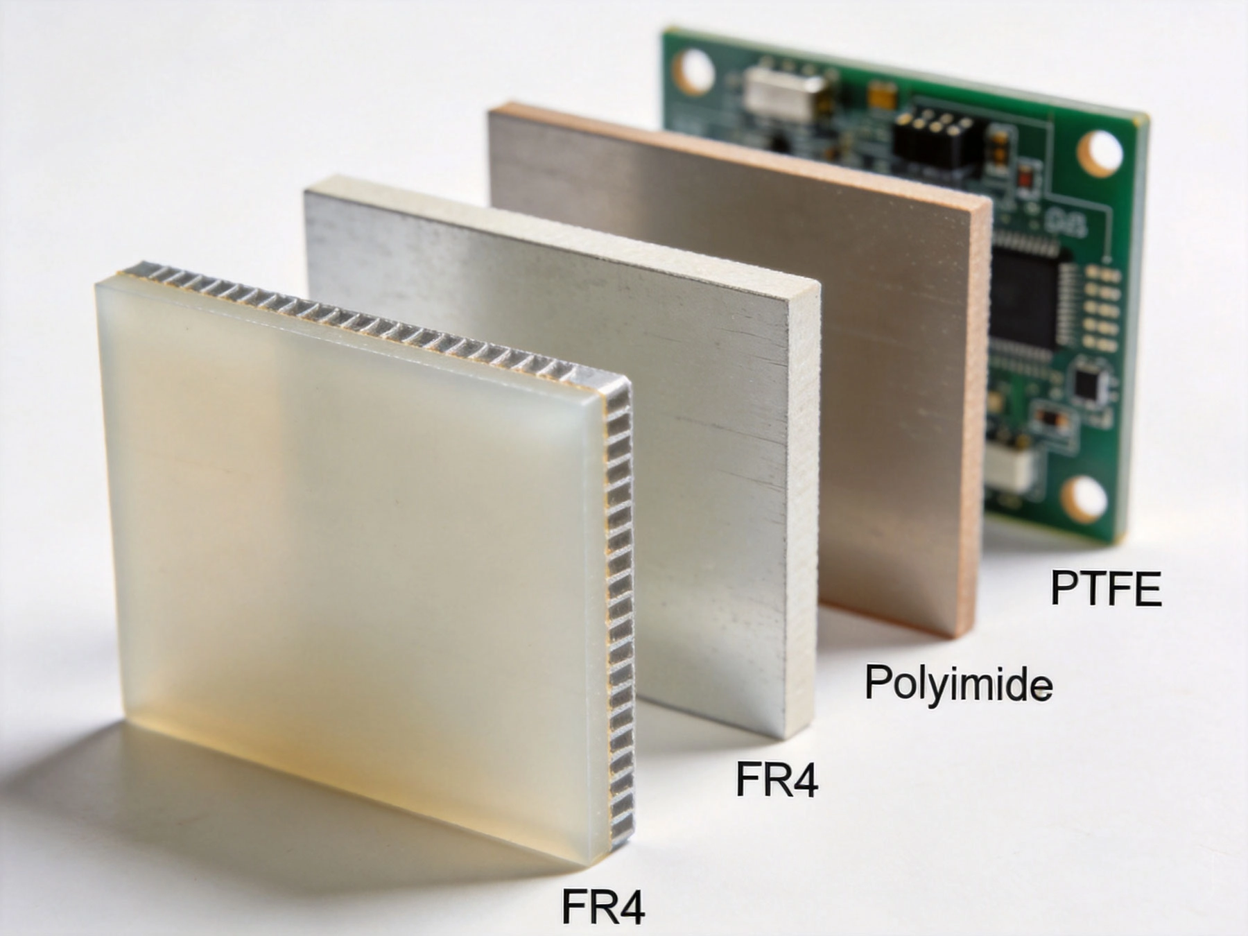
Before diving into specific materials, it's worth understanding why Dielectric Material selection is especially critical for Hdi Boards. In a conventional Multilayer Pcb, the dielectric properties of the substrate mainly affect Impedance Control and basic Signal Integrity. But in an HDI board with its fine trace geometries, Microvia structures, and Sequential Lamination process, the dielectric choice touches every aspect of the design simultaneously.
The high-frequency signals in 5G modules, AI accelerators, and high-speed data buses are unforgiving. They respond to even small variations in dielectric constant (Dk) and dissipation factor (Df). The Thermal Management challenge in densely packed HDI designs means the material must also serve as a heat pathway. And because Hdi Boards go through multiple lamination cycles at elevated temperatures and pressures, the dielectric must maintain its integrity and dimensional stability throughout. A material that works perfectly well in a 2-layer board can become a reliability liability in a 10-layer Hdi Stackup.
The dielectric constant (Dk) measures how much the material stores electrical energy in an electric field, relative to a vacuum. A higher Dk means greater capacitance between traces, which directly affects the characteristic impedance of transmission lines. In HDI designs with fine trace geometries and tight impedance tolerances (often ±5% or tighter), Dk consistency is paramount. Variations in Dk across the panel, through the thickness, or over temperature can cause impedance deviations that lead to signal reflection and integrity problems. Most PCB laminates have a Dk in the range of 3.8 to 4.8 at 1 GHz. For high-frequency applications, specialty materials with lower Dk values (2.5 to 3.5) offer advantages in signal propagation speed and reduced cross-talk.
The dissipation factor (Df) measures how much energy is lost as heat when the material is subjected to an alternating electric field. A lower Df means less signal loss, which is critical for high-frequency and high-speed digital applications. For signals operating at 10 GHz and above, or for high-speed serial links running at 25+ Gbps, the difference between a Df of 0.020 and 0.003 can mean the difference between a working design and one that fails margin testing.
Glass transition temperature (Tg) is the temperature at which the material transitions from a rigid, glassy state to a softer, rubbery state. For HDI PCBs that undergo multiple lamination cycles, a high Tg is essential — the material must maintain its dimensional stability and mechanical properties during the heat and pressure of sequential lamination. Standard FR-4 has a Tg around 130-140°C, which can be marginal for complex HDI stackups. High-Tg materials (170°C+) and ultra-high-Tg materials (250°C+) are increasingly common in advanced Hdi Applications.
The CTE describes how much the material expands when heated. This matters enormously in HDI boards because the dielectric material expands at a different rate than the copper traces and plated vias. During thermal cycling — from assembly reflow, from power on/off cycles, or from environmental temperature changes — this Cte Mismatch creates stress at the interfaces. In microvia structures, where the connection between layers is the weakest point, excessive CTE can lead to cracking and failure. The Z-axis CTE (through-thickness) is especially critical.
Some dielectric materials absorb moisture from the environment, which can cause problems during Hdi Manufacturing. Moisture absorbed into the substrate can flash to steam during lamination, creating voids and delamination. It can also affect the material's electrical properties in humid conditions. For applications in outdoor or automotive environments, low moisture absorption is an important selection criterion.
| Material Type | Dk @ 1GHz | Df @ 1GHz | Tg (°C) | Typical Use | Cost Level |
|---|---|---|---|---|---|
| Standard FR-4 | 4.2-4.5 | 0.020 | 130-140 | Consumer, cost-sensitive | Lowest |
| High-Tg FR-4 | 4.0-4.5 | 0.018 | 170-180 | Industrial, moderate HDI | Low |
| Multifunctional Epoxy | 4.0-4.3 | 0.016 | 150-170 | General Hdi Applications | Low-Medium |
| Polyimide | 3.5-4.2 | 0.015 | 250-270 | Aerospace, high reliability | High |
| PTFE (Teflon) | 2.1-2.3 | 0.001-0.002 | N/A | RF, microwave, 5G | Very High |
| Hydrocarbon Ceramic | 3.0-3.5 | 0.003-0.005 | 180-200 | 5G, mmWave, high-speed digital | High |
| Buildup Film (ABF) | 3.0-3.4 | 0.005-0.008 | 180-220 | Any layer HDI, fine-line applications | Medium-High |
FR-4 remains the workhorse of the PCB industry. Standard FR-4 is an epoxy-glass composite reinforced with woven fiberglass cloth. It's affordable, widely available, and has decades of manufacturing experience behind it. For Hdi Pcb applications, standard FR-4 has notable limitations: its relatively high Df (0.018-0.020) causes noticeable signal loss at frequencies above 5 GHz, its moderate Tg (130-140°C) means it can soften during multiple lamination cycles, and its CTE in the Z-axis is higher than ideal for reliable microvia structures.
High-Tg FR-4 formulations address some of these concerns by using modified epoxy systems with glass transition temperatures of 170°C or higher. This provides better thermal stability during sequential lamination and reduces the risk of delamination between cycles. High-Tg variants are a common choice for 1-N-1 and simple 2-N-2 HDI boards where the cost advantage of FR-4 is still meaningful.
Polyimide is the go-to material for high-reliability applications where thermal endurance is non-negotiable. With a Tg of 250°C or higher, polyimide boards can survive the most demanding assembly profiles, including lead-free solders with their higher peak reflow temperatures. It's the material of choice for aerospace applications, military systems, and down-hole drilling electronics where boards might see extreme thermal environments.
In HDI applications, polyimide offers excellent dimensional stability through multiple lamination cycles, reducing the risk of registration drift that plagues lower-Tg materials in complex stackups. Its lower CTE in the Z-axis compared to FR-4 provides better Microvia Reliability under thermal cycling. However, polyimide is significantly more expensive than FR-4, more difficult to process (it requires higher lamination temperatures and pressures), and absorbs more moisture, requiring careful pre-baking before lamination.
PTFE-based laminates — commonly known by the brand name Teflon — are the premier choice for radio frequency and microwave applications. With an exceptionally low Dk (2.1-2.3) and a Df as low as 0.001, PTFE materials deliver unmatched Signal Integrity at high frequencies. They're the material of choice for 5G millimeter-wave antenna modules, radar systems, satellite communications, and high-frequency test equipment.
Using PTFE in HDI applications is more complex than with conventional thermoset materials. PTFE has a very different processing window — it doesn't fully cure like epoxy and requires specialized preparation before plating. Microvia formation in PTFE is particularly challenging because the material doesn't respond well to standard desmear processes. Specialized plasma treatments and conductive paste fills are typically required.
Modern ceramic-filled PTFE composites have improved some of these processing challenges. These materials blend PTFE with ceramic particles to improve dimensional stability and Thermal Conductivity while retaining much of the electrical performance advantage. Rogers RO3000 and RO4000 series are well-known examples of ceramic-filled PTFE materials.
Hydrocarbon ceramic laminates represent one of the most important material categories for modern high-performance HDI applications. Materials like Panasonic Megtron, Isola I-Speed and I-Speed Delta, and Rogers 4350B fall into this category. They offer a compelling balance of electrical performance, thermal properties, and manufacturing compatibility that makes them ideal for 5G, AI accelerators, and high-speed digital applications.
These materials use a hydrocarbon resin system reinforced with ceramic fillers and/or fiberglass. The ceramic content lowers Dk and improves thermal conductivity, while the hydrocarbon resin provides good electrical performance and processing characteristics similar to conventional FR-4. The result is a material with Dk in the 3.0-3.6 range and Df of 0.003-0.005 — significantly better than FR-4 — while remaining processable using standard Pcb Manufacturing equipment.
For Hdi Pcb Manufacturing, hydrocarbon ceramics have become the preferred choice for flagship smartphones, networking equipment, and AI accelerator modules. Their high Tg (180-200°C) provides excellent thermal stability for sequential lamination, their low CTE reduces microvia stress, and their stable Dk over temperature and frequency simplifies impedance design.
Buildup films — also called adhesive films or ABF (Ajinomoto Build-up Film) — are thin dielectric layers specifically designed for the buildup portion of HDI stackups. Rather than using prepreg sheets (which are woven glass reinforced and relatively thick), buildup films are non-woven, film-type dielectrics that can be applied in very thin layers (typically 25-100 microns).
ABF and similar films offer several advantages for HDI PCB dielectric applications. Their uniform thickness improves impedance consistency across the board. They don't have the weave pattern that can cause Dk variation in woven glass prepregs — this is especially important for consistent microstrip and stripline performance. Films typically have lower Dk than glass-reinforced materials (3.0-3.4), which can be advantageous for high-frequency designs.
The processing requirements for buildup films differ from prepreg. They require careful temperature and pressure control during lamination, and film storage (typically refrigerated) and handling are more critical to prevent moisture absorption. Despite these challenges, any layer HDI boards almost universally use buildup films for at least some portion of their dielectric layers.
For mainstream consumer devices, the primary drivers are cost, manufacturing yield, and Miniaturization. High-Tg FR-4 or multifunctional epoxy systems are commonly used for the core layers, with buildup films for the outer buildup layers where the finest features and microvia density are required. Hydrocarbon ceramic materials are reserved for flagship models where the additional cost is justified by the performance demands of advanced processors and RF modules.
5G base stations and networking switches operate at frequencies and data rates where signal integrity is paramount. Hydrocarbon ceramic laminates are the dominant choice here, providing the low-loss performance needed for 28 Gbps and 56 Gbps SERDES channels. The material must also handle the thermal demands of high-power RF amplifiers and the mechanical requirements of outdoor environmental exposure.
Automotive Hdi applications face a unique combination of challenges: thermal cycling from engine compartment environments, vibration, reliability requirements governed by AEC-Q standards, and increasingly, high-speed data connections for Adas Systems. High-Tg FR-4 with enhanced UL ratings is common for body control modules, while hydrocarbon ceramics are increasingly specified for ADAS processors and infotainment systems.
The extreme reliability requirements of aerospace applications mean polyimide-based materials are the default choice for most HDI boards. For RF and microwave functions on aircraft and satellites, PTFE-based materials may be used where the frequency demands justify the processing complexity. Material selection is governed by military specifications (MIL-PRF) and must account for outgassing requirements in space applications.
Medical Electronics span a wide range from disposable diagnostic devices to high-end imaging equipment. For implantable devices, biocompatibility requirements may constrain material choices. For diagnostic and monitoring equipment, the priority is often Miniaturization (driving HDI adoption) combined with reliability. High-Tg FR-4 or hydrocarbon ceramics are common, depending on the complexity of the electronics.
One of the most frequent mistakes in HDI dielectric material selection is specifying a material with adequate Tg for the final assembly, but insufficient thermal stability for the manufacturing process. If your HDI board requires 4 sequential lamination cycles, each reaching 200°C, your dielectric material needs a Tg well above 200°C to maintain its structure and registration accuracy throughout. Always work backward from the manufacturing process requirements to set your minimum Tg specification.
Engineers often focus on the nominal Dk value of a material and overlook the tolerance — the range within which the actual Dk can vary. A material with a nominal Dk of 4.2 but a tolerance of ±5% gives you a range of 3.99 to 4.41. In a 50-ohm impedance design, this could easily push your impedance outside acceptable limits. Always specify materials with tight Dk tolerance, especially for fine-line HDI designs with tight impedance requirements.
Dielectric properties change with frequency. A material's Dk And Df at 1 GHz may be significantly different from its values at 10 GHz or 28 GHz. Make sure you're reviewing data at the frequencies relevant to your application. Many material datasheets now include frequency-dependent plots specifically for this reason. Don't design a 28 Gbps SERDES link using 1 GHz dielectric data — the signal loss calculations will be wildly inaccurate.
As boards become denser, there's growing interest in dielectric materials with embedded passive components — resistors and capacitors built into the substrate itself. These require dielectric formulations with very specific dielectric constants for capacitors or the ability to accept resistive inks for resistors. While still emerging, these materials could significantly reduce component count and board area.
As chip power densities increase, Thermal Management through the PCB substrate becomes more critical. New dielectric formulations incorporate ceramic fillers with high thermal conductivity while maintaining good electrical properties. These "thermal substrates" can conduct heat 5-10x better than standard FR-4, reducing the need for external heatsinks and enabling thinner, lighter designs.
Environmental regulations are pushing material suppliers to develop halogen-free and more sustainable dielectric formulations. While early halogen-free materials had significant processing and reliability drawbacks, newer formulations have largely closed the gap with traditional materials. Expect halogen-free options to become the default for consumer applications within the next few years.
Our engineering team has extensive experience with dielectric material selection for HDI applications across consumer electronics, automotive, medical, and industrial sectors. We can help you navigate the tradeoffs between performance, cost, and manufacturability to find the optimal material for your specific requirements. Contact us today for a consultation.
Yes, mixing different dielectric materials within a single Hdi Stackup is common and often beneficial. A typical approach might use a high-Tg FR-4 or hydrocarbon ceramic for the core (where thermal stability during sequential lamination matters most), with buildup films for the outer buildup layers (where thin, uniform dielectric is needed for fine-line routing). However, mixing materials requires careful consideration of CTE compatibility between layers — significant CTE mismatches can create stress concentrations at interfaces. Always validate mixed-material stackups with thermal stress testing and cross-section analysis.
Prepreg is a fiberglass-reinforced, partially cured (B-stage) epoxy sheet that softens and flows during lamination. Buildup film is a non-reinforced, film-type dielectric that cures during lamination without significant flow. Prepreg is typically used for core layers and thicker dielectric sections, while buildup films are used for the thin, uniform buildup layers in HDI. Films provide better thickness consistency and don't have the Dk variation caused by woven fiberglass weave patterns, making them better suited for high-frequency and fine-line designs.
The deciding factors are your signal frequency and data rate. If your highest-speed signals operate below 5 GHz and you're primarily concerned with digital logic (microcontroller communication, power distribution), standard FR-4 or high-Tg FR-4 will likely suffice. If you're designing for 5G (FR1 sub-6 GHz or mmWave), high-speed serial links at 10+ Gbps, or any RF application, you need a low-loss material (hydrocarbon ceramic or PTFE). As a rough rule: if you're measuring signal integrity margin issues or eye diagram closure at high data rates, your material's Df is likely a significant contributor.
Dielectric thickness directly affects several key parameters. Thinner dielectrics between signal layers and ground planes create higher capacitance per unit length, which means you need narrower traces to achieve the same impedance — but thinner dielectrics also reduce loop inductance, which can be beneficial for high-speed signals. In HDI designs using buildup films, very thin dielectrics (25-50 microns) enable tight coupling between layers for controlled impedance routing. However, thinner dielectrics also provide less insulation between layers, which matters for high-voltage designs.
A complete dielectric material specification for HDI should include: the material type and brand/designation (e.g., Panasonic Megtron 6 or Isola I-Speed Delta), nominal Dk And Df at your operating frequency, Dk tolerance specification, Tg minimum, CTE values for both X-Y and Z axes, moisture absorption percentage, UL flammability rating, and any special processing notes like sequential lamination compatibility. When working with a manufacturer, share your material specification early — they may have recommendations based on their specific equipment and process capabilities.
Exploring the 6 Types of HDI Structures: From Type I to Any-LayerAugust/14/2026
Effective Thermal Management Strategies for High-Density PCBsMay/28/2026
How to Use Thermal Simulation Software to Optimize HDI LayoutsJuly/29/2026
The Role of Thermal Vias in Dissipating Heat from HDI BoardsJune/09/2026
Copper Coin and Embedded Heat Sinks: Advanced Cooling for HDIJuly/08/2026
The Evolution of PCB Technology: From Standard Multilayer to HDIJune/02/2026
Precision in HDI FabricationJune/04/2026
The Role of HDI in Smart Grid and Energy Storage SystemsAugust/06/2026