Open Nav

Automotive Electronics endure mechanical environments that would destroy most consumer PCBs. Vibration from engines and road surfaces, shock from impacts and braking, and thermal cycling from daily temperature swings create a uniquely demanding physical environment. High-density Interconnect (HDI) boards in modern vehicles must maintain electrical performance while surviving mechanical stresses that would crack traces, dislodge components, and fracture solder joints in conventional assemblies.
Designing Hdi Boards for automotive vibration and shock resistance requires thinking beyond electrical performance to consider mechanical survivability. The same fine-pitch components, Microvias, and dense routing that enable HDI functionality also create failure points under mechanical stress. This guide walks through the design strategies, material choices, and validation methods that create Hdi Boards that survive the automotive environment without sacrificing the density advantages that Hdi Technology provides.
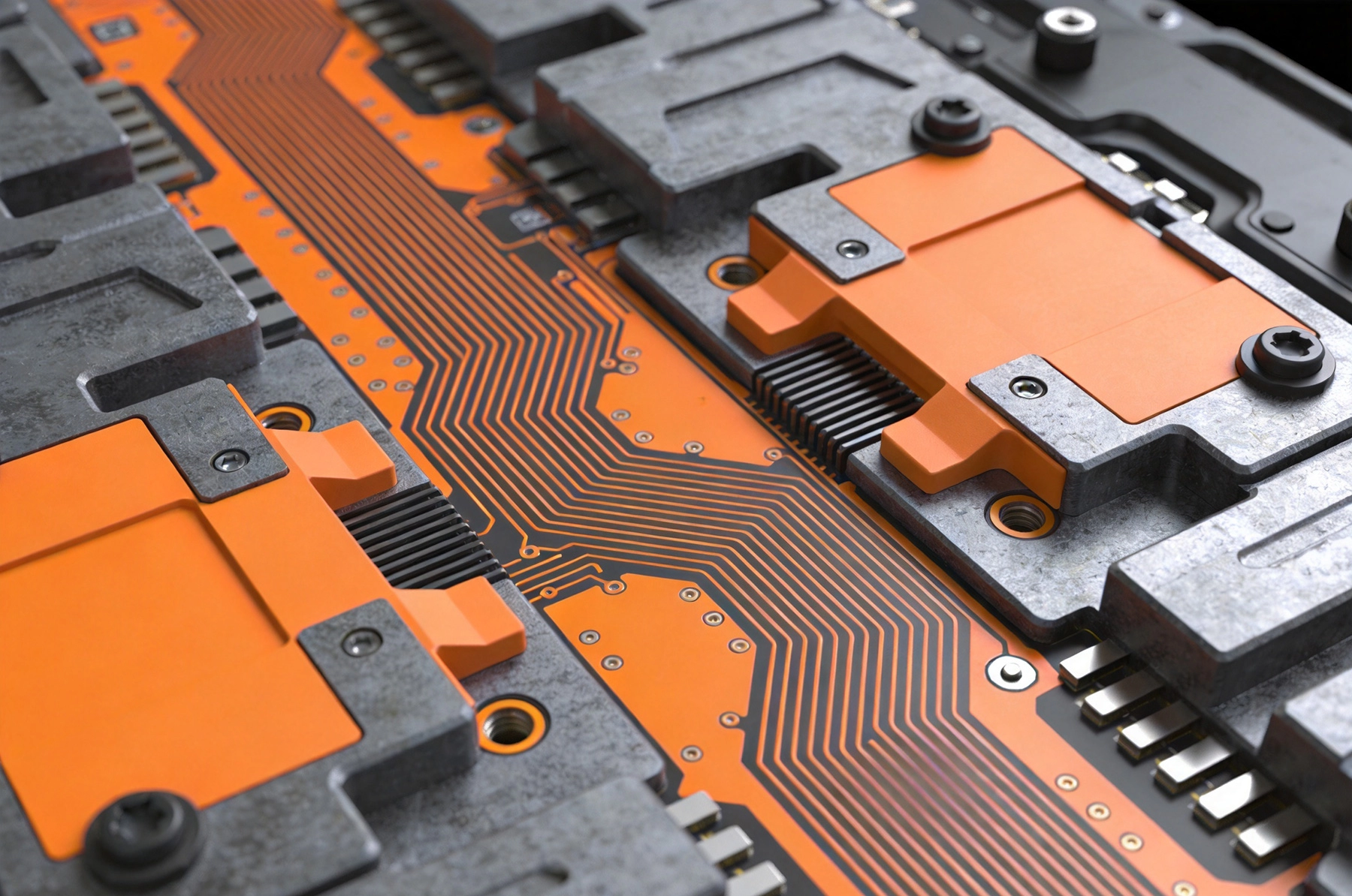
Before addressing design solutions, it's essential to understand the mechanical challenges automotive boards face. Different vehicle environments create different stress profiles, and matching your design to the specific deployment location is crucial for effective vibration and shock resistance.
Automotive vibration comes from multiple sources with different frequency ranges and amplitudes. Engine vibrations are typically low-frequency with high amplitude, especially in diesel engines with significant torque pulses. Road-induced vibrations have higher frequencies and variable amplitudes depending on road surface roughness. Electric vehicles remove engine vibrations but introduce motor whine vibrations at high frequencies from motor switching and inverter operation.
Vibration is rarely a single-frequency sine wave in real vehicles — it's a complex combination of frequencies that vary based on engine speed, road conditions, vehicle loading, and driving style. Board designs that survive simple sine wave testing often fail under complex, multi-frequency vibration because resonant frequencies interact in unexpected ways.
Shock events include both routine occurrences like pothole impacts and door closing, and infrequent but severe events like accidents. Routine shocks typically involve 10-50G acceleration over milliseconds, while accident-level shocks can exceed 100G with longer duration. Boards must survive both routine operational shocks and emergency-level impacts without losing functionality.
Shock directionality matters more than many designers realize. A board that handles vertical shock well might fail under lateral or torsional shock because different components and mounting structures respond differently to stress from different directions. Automotive vibration and shock specifications often specify different G-level requirements for different axes.
The most dangerous vibration occurs at the board's natural resonant frequencies, where relatively small input vibration can produce large displacements and stress. Every PCB assembly has multiple resonant modes determined by board dimensions, component mass distribution, mounting configuration, and material properties. When environmental vibration frequencies coincide with these resonant frequencies, stress amplification creates failure risks.
Resonance problems are particularly problematic because they're nonlinear — a small change in board dimensions or component placement can shift resonant frequencies by tens or hundreds of Hertz, taking you out of the danger zone or into it. This is why board modifications that seem minor can dramatically change vibration susceptibility.
The materials you choose for your Automotive Hdi board set the foundation for mechanical resilience. While standard FR4 materials work for many applications, automotive environments often demand enhanced materials that maintain performance under thermal and mechanical stress.
Standard FR4 with Tg around 130°C performs adequately for some automotive applications, but higher-Tg materials provide better mechanical stability at elevated temperatures common in under-hood environments. Materials with Tg above 170°C maintain stiffness and strength better at the 125°C+ temperatures that Automotive Electronics must tolerate.
Beyond Tg, consider CTE (coefficient of thermal expansion) matching between substrate and components. Large CTE mismatches create thermally induced stresses during temperature cycling that weaken solder joints and create microcracks in the board itself. Materials with CTE closer to silicon and ceramic components reduce this mismatch and improve thermal cycling reliability.
For applications with exceptional vibration requirements, specialized materials like polyimide-filled FR4 or ceramic-filled composites provide enhanced mechanical properties. These materials trade cost and manufacturability for superior stiffness, damping, and thermal stability — worthwhile trade-offs when vibration is the primary failure concern.
Heavier copper weights improve mechanical strength but also add mass that affects vibration characteristics. A 2 oz copper board is significantly stiffer than an equivalent 0.5 oz copper board, but the increased mass shifts resonant frequencies and increases the kinetic energy when vibration does occur. Choose copper weight based on both current-carrying requirements and mechanical considerations.
Electroless nickel immersion gold (ENIG) plating provides robust surface finish for high-density interconnects, but the nickel layer is relatively brittle and can crack under repeated flexing. Alternative finishes like ENEPIG (electroless nickel electroless palladium immersion gold) add palladium layers that improve flexibility while maintaining solderability.
Through-hole plating thickness affects mechanical strength of vias, particularly Microvias that HDI boards use extensively. Standard 25-micron plating may be inadequate for high-vibration applications — specify thicker plating (30-35 microns) for via barrels that must survive mechanical stress.
Conformal coating provides a mechanical barrier that ties components together and distributes vibration forces. Silicone coatings offer excellent flexibility across temperature ranges but have limited mechanical strength. Polyurethane coatings provide better mechanical toughness but have narrower temperature ranges. Epoxy coatings offer the best mechanical strength but are brittle and crack under thermal cycling.
For vibration-critical applications, consider applying coating at greater thickness or using multiple coating layers for enhanced mechanical coupling. The coating's primary benefit isn't just environmental protection — it's the mechanical coupling that reduces component relative motion under vibration stress.
How you stack and design the layers in your HDI board significantly affects mechanical performance. Symmetric constructions, balanced layer counts, and strategic placement of rigid and flexible layers create boards that maintain integrity under stress.
Symmetric stack-ups with equal layer counts above and below the center core reduce warpage and maintain flatness during thermal cycling. This symmetry also balances mechanical stresses that occur during vibration because forces distribute evenly rather than concentrating on one side of the board.
For HDI boards with Sequential Lamination, each build-up layer should be added symmetrically when possible. If your design requires asymmetric layer counts, compensate with copper weight variations or thickness variations that maintain overall symmetry. A 2-layer core with 2 build-up layers on each side maintains the symmetry advantage.
Metal core boards or boards with integrated stiffeners provide dramatically improved vibration resistance by creating rigid structures that resist deformation. Aluminum cores provide high stiffness-to-weight ratio, while copper cores provide both stiffness and Thermal Conductivity. Choose core material based on the balance between mechanical and thermal requirements.
When using stiffeners, integrate them into the layer stack-up during fabrication rather than bonding them as separate components. Fabrication-integrated stiffeners maintain better thermal and mechanical coupling than bonded approaches, though bonded stiffeners allow repair and replacement.
Balance copper distribution across layers to prevent warpage and stress concentration. A board with heavy copper on outer layers but minimal copper on inner layers creates an unbalanced structure that warps under thermal and mechanical stress. Distribute copper planes and routing evenly across layers to maintain mechanical balance.
For power distribution layers, consider splitting high-current traces across multiple layers to avoid heavy copper concentration on a single layer. This approach reduces stress concentration while maintaining current capacity through parallel conduction.
Where you place components and which components you select directly affects vibration survivability. Large heavy components create stress concentration points, while small fine-pitch components create solder joint vulnerabilities. Strategic placement and careful selection reduce vibration-related failure risks.
Component mass creates inertial forces during vibration and shock. A 10-gram connector accelerates under vibration, generating forces that stress its solder joints and surrounding copper pads. Distribute mass evenly across the board rather than concentrating heavy components in one area, which creates localized stress and shifts resonant frequencies.
Place heavy components near board supports or mounting points where mechanical support is greatest. A heavy connector near the board edge will experience more deflection than the same connector mounted near a mounting boss or chassis attachment point. When heavy components can't be placed near supports, add local stiffening or additional mounting in that area.
Component orientation affects how vibration forces load solder joints. A rectangular chip component oriented with its long axis parallel to vibration direction experiences different stress than the same component rotated 90 degrees. While rotation won't make a component vibration-proof, it does change the stress distribution on solder joints.
Align components to minimize cantilever effects on their leads. Components with leads that extend beyond the package body are vulnerable to vibration because the leads act as cantilevers that flex and fatigue. Where possible, use components with short leads or ball-grid packages that distribute forces across multiple solder joints.
Connectors and interface components are particularly vulnerable to vibration because they experience external mechanical forces from mating cycles and cable movement. Use board-mounted connectors with multiple mounting points that distribute mechanical stress rather than relying on solder joints alone for mechanical integrity.
Provide mechanical support for external connectors. Board-mounted connectors for external interfaces should have chassis-mounted supports that transfer mechanical loads directly to the enclosure rather than through the board. This support approach is especially important for connectors subjected to cable movement during vehicle operation.
HDI boards rely heavily on microvias for high-density interconnects. These microvias are vulnerable to vibration and shock because their small diameter and aspect ratios create stress concentrations. Proper Microvia Design and reinforcement reduce failure risks.
Microvia aspect ratio (depth to diameter) strongly influences mechanical robustness. High aspect ratio microvias are more prone to cracking under stress because longer drill holes create greater stress concentrations and plating thickness variations along the via barrel.
For automotive applications, target aspect ratios below 1:1 when possible. A 0.1mm diameter via should not exceed 0.1mm in depth. This may require more sequential laminations to achieve your desired layer count, but the reliability improvement justifies the additional process complexity in vibration-critical applications.
Microvia placement affects stress distribution. Clustering many microvias in small areas creates stress concentrations that become failure initiation points. Distribute microvias evenly across the board area, and avoid placing microvias directly under component bodies where mechanical forces concentrate.
Use Via-in-pad construction carefully for vibration-critical applications. Via-in-pad eliminates dogbone routing but creates stress points directly under component pads where vibration forces load solder joints. When via-in-pad is necessary for density, use filled and capped vias that distribute stress across the pad area rather than creating stress points at the pad edge.
Standard through-holes in HDI boards provide mechanical reinforcement in addition to electrical interconnection. The plated barrel of a through-hole creates a column that resists board flexing and provides distributed support for the board structure.
Consider strategic through-hole placement even when HDI design could eliminate them. Adding non-functional through-holes in high-stress areas provides mechanical reinforcement without requiring redesign of the routing. These reinforcement vias add minimal cost but significantly improve mechanical integrity.
How the board mounts to its enclosure determines how external vibration transfers to the board assembly. Proper mounting design isolates the board from severe vibration while providing secure attachment that prevents board movement.
Mounting points should be distributed around the board perimeter rather than concentrated in one area. Four mounting points at board corners provide better vibration resistance than two mounting points on one edge. For larger boards, add intermediate mounting points to reduce unsupported spans.
Place mounting points at positions that support heavy components and connector assemblies. Mounting under a large connector or power module transfers mechanical forces directly to the chassis rather than through the board.
Board-level vibration isolation using elastomeric mounting grommets or isolation mounts reduces vibration transmission from the vehicle chassis to the PCB. Isolation is particularly valuable for high-frequency vibration that the board might be susceptible to at its resonant frequencies.
When using isolation mounts, consider both isolation effectiveness and static stiffness. Highly compliant isolation mounts protect against vibration but allow board movement that can cause cabling stress or connector damage. Balance isolation stiffness against the need for mechanical security.
The enclosure should provide rigid support rather than just attachment points. A flexible enclosure allows board movement that defeats mounting strategies. Use rigid enclosures with adequate wall thickness, and add internal supports and ribs that prevent flexing.
For boards in flexible enclosures like wire harnesses or battery modules, consider adding local stiffening around the mounting area. A metal stiffener or reinforcement plate bonded to the enclosure at mounting points provides local rigidity that prevents board movement while the overall enclosure remains flexible.
Testing validates that your design actually withstands the mechanical environment. Automotive testing standards provide baseline requirements, but additional testing tailored to your application catches problems that standard tests miss.
Automotive vibration testing follows standards like ISO 16750-3 or customer-specific specifications. These tests typically include random vibration profiles covering 5-2000 Hz frequency ranges at specified acceleration levels. Testing applies vibration in three axes (X, Y, Z) for specified durations.
Pay particular attention to the frequency ranges that match your expected operating conditions. A board installed on engine mounts experiences different vibration profiles than one mounted on the chassis. Use test profiles that match your specific mounting location rather than generic automotive profiles.
Shock testing simulates impact events like potholes, door slamming, and braking. Standard tests apply half-sine or trapezoidal shock pulses at specified G-levels for specified durations. Directionality matters — tests typically require three axes and may specify different G-levels for different directions.
For safety-critical systems like ABS or stability control, consider testing beyond specification to determine safety margins. Finding that your board fails at 80G when specification requires 50G helps you understand how close you are to failure limits and whether design margin is adequate.
Highly Accelerated Life Testing (HALT) and Highly Accelerated Stress Screening (HASS) go beyond standard testing to find design weaknesses. HALT progressively increases stress levels until failures occur, revealing margins and failure modes. HASS applies accelerated stress to screen production units for defects.
HALT testing for vibration and shock identifies resonant frequencies and shock levels where failures occur. Finding that your board survives specification tests but fails at slightly higher levels provides warning about design margin. HALT is particularly valuable for HDI boards because their complex structures create unexpected vibration modes that standard testing might miss.
Lab testing provides confidence, but vehicle testing validates performance in the actual environment. Mount instrumented boards in test vehicles and collect vibration data under real driving conditions. Compare actual vibration to test specifications to ensure your testing captures real-world conditions.
Operational testing also reveals coupling between vibration and other environmental stresses like temperature. A board that passes vibration testing at room temperature might fail when vibration testing occurs at elevated temperature where materials soften. Combined environmental testing captures these interaction effects.
Understanding how Automotive Hdi boards typically fail under vibration and shock helps you design against these failure modes before they occur in the field.
Solder joint cracking is the most common vibration failure mode. Cracks initiate at stress concentrations and propagate with repeated cycling. Large components with few solder joints (like connectors) are particularly vulnerable because each joint carries a disproportionate share of the mechanical load.
Prevention includes increasing solder joint count through larger component footprints or additional mechanical supports, using stress-relief designs that distribute forces across multiple joints, and selecting lead-free solder alloys with better fatigue resistance than SnPb solders.
Traces and vias crack when board flexing creates tensile stress that exceeds material strength. Traces crossing board edges or transitioning between stiff and compliant areas are particularly vulnerable. Microvias with high aspect ratios crack at the via barrel where plating is thinnest.
Prevention includes adding strain relief at trace transitions, avoiding sharp bends in routing that create stress points, and designing microvias with moderate aspect ratios. Adding ground traces or copper pours around critical traces provides mechanical support that distributes stress.
Component packages themselves can crack under vibration and shock stress. Plastic packages are particularly vulnerable because the epoxy molding compound can fracture under repeated stress. Ceramic packages are less prone to cracking but more susceptible to solder joint fatigue because they're stiffer and transfer more stress to solder joints.
Prevention includes selecting components with proven automotive reliability, providing additional mechanical support for vulnerable components, and avoiding component placement in high-stress areas like near board edges or mounting points.
Mounting screws can loosen under repeated vibration, creating board movement that generates failures elsewhere. This failure mode is particularly insidious because it may not cause immediate problems but creates progressive degradation that leads to failure after extended operation.
Prevention includes using thread-locking compounds on all mounting screws, specifying nyloc nuts or lock washers, and designing mounting features that prevent screw rotation. Regular inspection programs check mounting security in fielded equipment.
Designing automotive HDI boards for vibration and shock resistance requires attention to every aspect of design — from material selection through component placement to mounting strategy. Vibration and shock aren't afterthoughts to be handled by adding a thicker board or more mounting screws — they're fundamental design requirements that influence every decision.
Start by understanding the specific mechanical environment your board will face. Engine compartment boards face different vibration profiles than interior electronics, and boards on electric vehicles face different profiles than conventional vehicles. Match your design to the actual environment rather than assuming generic automotive requirements apply equally to all locations.
Material choices set mechanical performance limits. Choose substrates with appropriate Tg and CTE for your temperature and vibration requirements. Select copper weights that balance electrical and mechanical needs. Specify conformal coatings that provide both environmental protection and mechanical coupling.
Design board stack-ups for mechanical balance and stiffness. Symmetric constructions reduce warpage and stress concentration. Metal cores and stiffeners provide exceptional vibration resistance when required. Balance copper distribution across layers to prevent unbalanced structures.
Place components strategically to minimize stress concentrations. Distribute mass evenly across the board. Place heavy components near mounting supports. Choose component orientations that reduce solder joint stress. Provide mechanical support for connectors and interfaces.
Test thoroughly using both standard specifications and accelerated methods. Standard testing validates compliance, but HALT/HASS testing reveals design weaknesses and safety margins. Vehicle testing captures real-world conditions that lab tests miss. Combined environmental testing catches interaction effects that single-stress testing misses.
Automotive HDI boards that survive vibration and shock aren't designed by accident — they're created through systematic attention to mechanical design requirements. Every design decision affects mechanical resilience, and successful designs balance electrical performance requirements with mechanical survivability needs throughout the development process.
ISO 16750-3 provides the baseline standard for automotive vibration testing. Many automotive manufacturers have their own specifications that supersede or augment ISO requirements. Verify the specific standards required by your customer before specifying vibration testing profiles. Testing typically covers 5-2000 Hz frequency ranges with acceleration levels ranging from 1G to 10G depending on mounting location.
Resonant frequency calculation requires considering board dimensions, material properties, component mass distribution, and mounting configuration. Finite element analysis (FEA) software provides accurate predictions but requires significant expertise. Simplified hand calculations using board stiffness formulas provide approximate resonant frequencies for rectangular boards with simple mounting. For accurate results, physical vibration testing with modal analysis measures actual resonant frequencies rather than relying on calculations.
Yes, when designed and manufactured properly. Microvias with aspect ratios below 1:1, adequate plating thickness (30+ microns), and proper placement away from stress concentrations perform reliably in automotive applications. Avoid clustering microvias in small areas, and use filled and capped vias for via-in-pad applications. Your manufacturing partner should validate Microvia Reliability through accelerated life testing before production.
Vibration testing applies continuous oscillatory motion typically at multiple frequencies simultaneously. Shock testing applies single, high-acceleration impulses like those from impacts or sudden stops. Vibration causes fatigue failures from repeated cycling, while shock can cause immediate failures from excessive stress. Automotive specifications typically require both types of testing because vehicles experience both continuous vibration and intermittent shock events.
Conformal coating improves vibration resistance by mechanically coupling components to the board and distributing forces. The coating prevents relative motion between components and the board, reducing stress on solder joints and component terminations. Thicker coatings and materials with higher modulus provide greater mechanical coupling. Select coating materials that maintain flexibility across your operating temperature range to avoid cracking that would compromise protection.
Vibration and shock resistance isn't optional for automotive electronics — it's essential. Every board that goes into a vehicle faces mechanical stress that would destroy unprotected assemblies. By designing for these requirements from the start, you create HDI boards that deliver automotive density without sacrificing the reliability that automotive customers demand.
Understanding the Core Differences Between HDI and Traditional PCBsJuly/02/2026
Meeting AEC-Q100 Reliability Standards for Automotive HDISeptember/14/2026

HDI Solutions for In-Vehicle Infotainment (IVI) and ClustersAugust/07/2026

The Role of HDI in Avionics and Flight Control SystemsAugust/13/2026

How HDI Technology Supports Advanced Driver Assistance Systems (ADAS)June/25/2026
The Role of HDI in Robotics and Motion Control SystemsAugust/10/2026
Designing HDI Backplanes for High-Performance Networking EquipmentOctober/16/2026
Managing Layer-to-Layer Registration Accuracy in Multilayer HDIOctober/09/2026