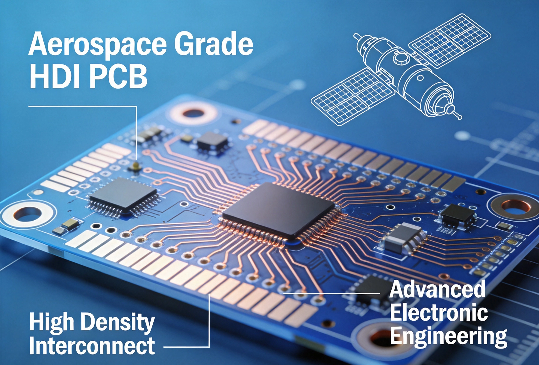
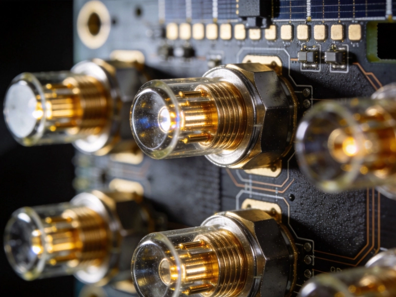
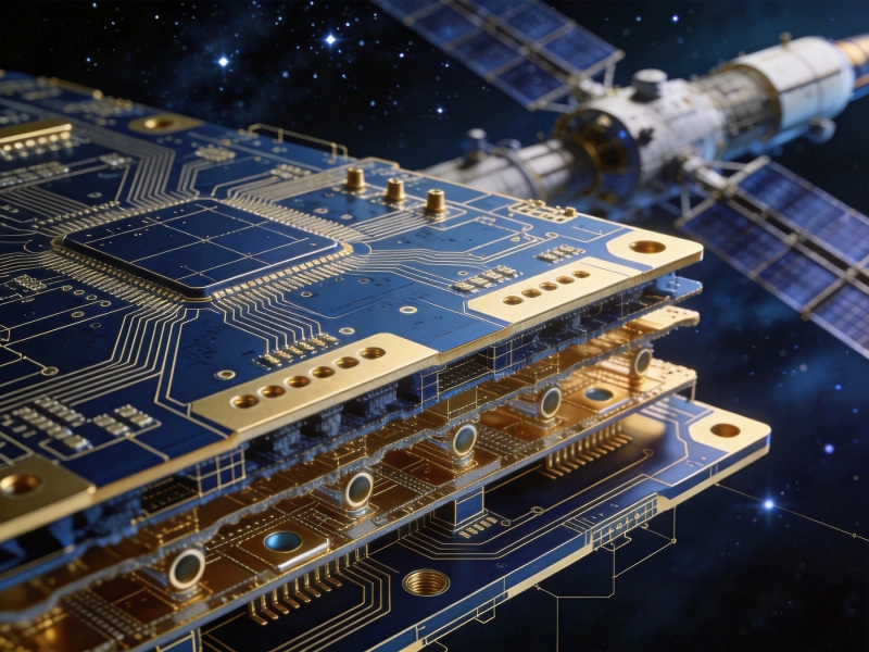
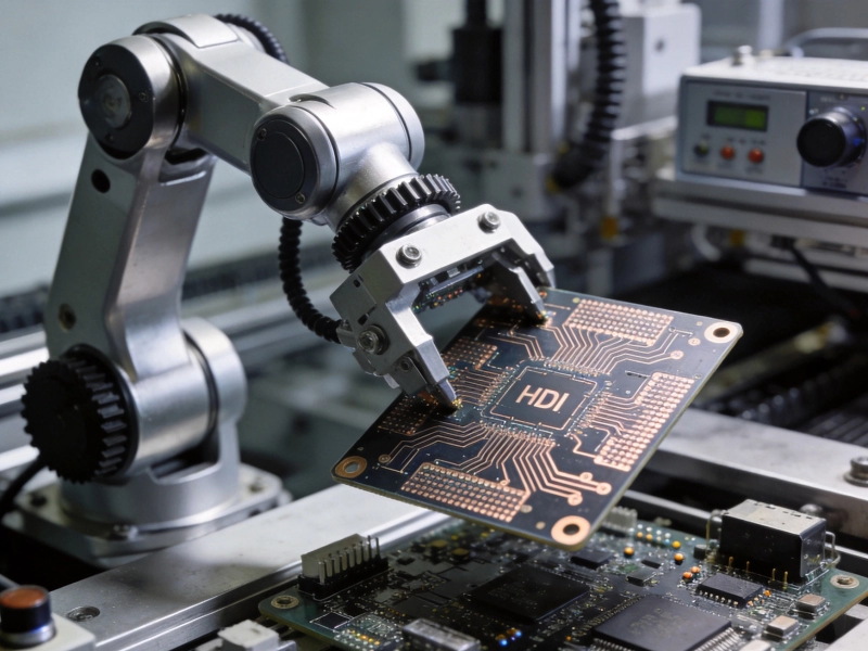
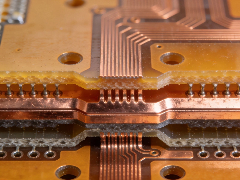
High Density Interconnect (HDI) technology has revolutionized Aerospace Electronics by enabling unprecedented functionality within compact, lightweight form factors. As aerospace systems push toward greater performance, reduced weight, and increased reliability, Hdi Boards have become essential for meeting these demanding requirements. However, the extreme environments encountered in aerospace applications—from the vacuum of space to the intense vibrations of launch—present unique challenges that demand specialized design approaches, material selection, and manufacturing processes. Designing Hdi Boards that not only survive but thrive in these conditions requires deep understanding of environmental stressors, careful material engineering, and meticulous attention to design details that might be inconsequential in terrestrial applications.
This comprehensive guide explores the critical aspects of designing HDI boards for extreme aerospace environments, covering material selection, design considerations, manufacturing requirements, and validation approaches that ensure reliable performance under the most demanding conditions imaginable.

Understanding Extreme Aerospace Environments
Aerospace environments subject electronic assemblies to conditions far beyond typical commercial operating ranges. Understanding these environmental challenges represents the first step in designing HDI boards that can withstand them:
Temperature Extremes
Aerospace Electronics experience extreme temperature variations that would destroy most commercial PCBs. Spacecraft face temperature ranges from -150°C in shadow to +150°C in direct sunlight, depending on orbit and thermal control systems. Aircraft encounter rapid temperature changes from -55°C at high altitude to +85°C or higher in engine compartments. These thermal cycles create mechanical stress as different materials expand and contract at different rates, potentially causing delamination, via failure, or solder joint cracking. HDI boards must accommodate these thermal stresses while maintaining electrical performance throughout the temperature range.
Vibration and Shock
Launch vehicles subject payloads to intense vibration across a broad frequency spectrum, from low-frequency structural vibrations to high-frequency engine-induced oscillations. Random vibration levels can exceed 20 Grms in some launch environments, with specific frequency bands creating resonant responses that amplify stress on board assemblies. Pyrotechnic shock events during stage separation or deployment create transient acceleration spikes exceeding 10,000 Gs. These mechanical stresses can cause component detachment, solder joint failure, via cracking, or laminate delamination if boards aren't properly designed to accommodate them.
Radiation Exposure
Space environments expose electronics to various forms of radiation that can degrade performance and cause failures. Total ionizing dose (TID) radiation accumulates over time, causing gradual degradation of semiconductor devices and dielectric materials. Single event effects (SEE) from high-energy particles can cause bit flips, latch-up, or permanent damage in integrated circuits. Charged particles can also cause charging effects in dielectric materials, potentially leading to electrostatic discharge (ESD) events. HDI boards must incorporate radiation-hardening approaches and select materials that maintain properties under radiation exposure.
Vacuum ConditionsSpace vacuum presents unique challenges for HDI boards. Outgassing of volatile materials from PCB laminates, solder mask, and conformal coatings can contaminate sensitive optical surfaces or interfere with spacecraft systems. Differential pressure between sealed and unsealed cavities can cause mechanical stress. The absence of atmospheric cooling forces changes Thermal Management approaches, requiring conduction-based heat transfer rather than convection. Materials must be selected and processed to minimize outgassing while maintaining mechanical and electrical properties in vacuum.
Humidity and Condensation
Aircraft and ground-based aerospace equipment encounter humidity extremes that can cause corrosion, leakage currents, and short circuits. Rapid altitude changes cause condensation as humid air cools below its dew point, potentially causing water accumulation on board surfaces. Salt spray environments in naval aviation create particularly aggressive corrosion conditions. HDI boards must incorporate protection against moisture ingress through proper sealing, conformal coating, and material selection that resists moisture absorption.
Material Selection for Aerospace HDI Boards
Material selection represents one of the most critical decisions in aerospace Hdi Board Design. Standard FR-4 materials often prove inadequate for extreme aerospace environments:
Advanced Laminate Materials
Aerospace HDI boards typically require advanced laminate materials with superior thermal and mechanical properties:
- Polyimide laminates: Offer excellent thermal stability (-200°C to +260°C), low outgassing, and good mechanical properties. Popular choices include Kapton, Apical, and Upilex materials. Polyimide maintains electrical properties across extreme temperature ranges and resists radiation degradation better than standard epoxies.
- Cyanate ester laminates: Provide excellent dimensional stability, low moisture absorption, and good radiation resistance. Materials like RO4000 series offer good high-frequency performance suitable for aerospace applications.
- PTFE-based laminates: Excel in high-frequency applications but require special processing due to PTFE's thermal expansion characteristics. Materials like RO3000 series provide excellent electrical properties for microwave and RF applications.
- Ceramic-filled laminates: Offer enhanced Thermal Conductivity for power applications while maintaining good electrical properties. Materials like RT/duroid provide stable performance across temperature ranges.
Copper Foil Selection
Copper foil characteristics significantly affect HDI board performance in aerospace environments:
- Reverse-treated foil: Provides better adhesion to dielectric materials, reducing delamination risk under thermal cycling stress. The roughened side bonds to the dielectric while the smooth side provides good solderability.
- High-temperature annealed foil: Reduces residual stress in copper, improving mechanical stability under thermal cycling. Annealed foil withstands repeated thermal expansion without work hardening.
- Low-profile foil: Reduces surface roughness for fine-line capabilities while maintaining adequate adhesion. Low-profile foils enable the fine features required for Hdi Technology.
Solder Mask and Surface Finish
Protective coatings and surface finishes must withstand aerospace environmental challenges:
- High-temperature solder mask: Standard LPI solder masks may not withstand extreme aerospace temperature ranges. High-temperature formulations maintain adhesion and electrical insulation across temperature extremes.
- Low-outgassing solder mask: Formulated specifically for space applications to minimize volatile emissions that could contaminate optical systems or interfere with spacecraft operations.
- ENIG (Electroless Nickel Immersion Gold): Provides excellent corrosion resistance and shelf life, making it suitable for harsh environments. However, nickel's magnetic properties may be problematic for some applications.
- Immersion Silver: Offers excellent electrical conductivity and solderability but requires careful packaging to prevent tarnishing before assembly.
- OSP (Organic Solderability Preservative): Provides flat, solderable surfaces but may not offer sufficient long-term protection for some aerospace applications.
Conformal Coating Materials
Conformal coating provides essential protection against moisture, contaminants, and mechanical stress:
- Parylene: Excellent aerospace coating with conformal coverage, low outgassing, and good dielectric properties. Provides excellent protection against moisture and contaminants while maintaining flexibility for thermal cycling.
- Silicone: Offers good thermal cycling performance and flexibility but may have higher outgassing than other options. Provides good moisture protection and mechanical shock absorption.
- Polyurethane: Good abrasion and chemical resistance but may crack under extreme thermal cycling. Suitable for applications with moderate temperature ranges.
- Epoxy: Excellent chemical and moisture resistance but may be brittle under thermal cycling. Best suited for applications with stable temperature environments.
HDI Design Considerations for Aerospace Environments
Hdi Technology introduces specific design challenges that become more critical in aerospace applications:
Microvia Design and Reliability
Microvias represent one of HDI's key enablers but also present reliability challenges in aerospace environments:
- Via Filling: Filled Microvias provide better mechanical stability and prevent moisture ingress. Fill materials must match thermal expansion characteristics of surrounding materials to prevent stress concentration.
- Aspect ratio limits: Maintain conservative aspect ratios (typically 0.8:1 or better) to ensure reliable plating and reduce failure risk under thermal stress. Deeper vias may not plate consistently and are more prone to cracking.
- Via-in-pad design: Provides better thermal and electrical performance but requires careful processing. Filled and capped vias prevent solder wicking and ensure reliable solder joints.
- Thermal relief for via connections: Balance thermal conduction requirements with stress relief to prevent thermal stress concentrations around vias.
Layer Stackup Design
Proper layer stackup design ensures reliable performance under aerospace environmental stresses:
- Symmetrical stackups: Use symmetrical layer arrangements to minimize warpage and stress during thermal cycling. Asymmetric stackups cause boards to bow or twist as temperatures change.
- Balance copper distribution: Ensure similar copper amounts on opposite sides of the centerline to prevent differential expansion that causes warpage.
- Dielectric thickness consistency: Maintain consistent dielectric thickness across layers to prevent stress concentrations. Varying thicknesses create differential expansion rates.
- Power plane placement: Position power and ground planes to provide mechanical stiffening while meeting electrical requirements. Planes help reduce board flexure under vibration.
Trace Geometry and Spacing
Trace design must balance electrical requirements with mechanical reliability:
- Width for current carrying: Size traces appropriately for current requirements with derating for aerospace environments. Consider reduced thermal conduction in vacuum environments.
- Minimum bend radius: Avoid sharp bends that create stress concentration points. Use curved traces or 45-degree angles rather than 90-degree bends.
- Teardrop connections: Use teardrop pads where traces connect to vias or pads to distribute stress and prevent cracking under thermal cycling.
- Increased spacing: Provide wider spacing between traces than minimum design rules allow to accommodate potential conductor movement under thermal stress and reduce short-circuit risk from debris or conductive contamination.
Thermal Management Design
Thermal Management becomes critical in aerospace environments where cooling options may be limited:
- Thermal Vias: Use arrays of Thermal Vias to conduct heat from hot components to heat sinks or mounting surfaces. Via arrays provide more reliable thermal paths than single vias.
- Copper plane utilization: Maximize copper plane area for heat spreading. Planes provide efficient thermal conduction paths to mounting surfaces or heat sinks.
- Component placement: Position high-power components near Heat Dissipation paths. Consider thermal coupling between components to prevent hot spots.
- Thermal isolation: Isolate temperature-sensitive components from heat sources using thermal barriers or isolation techniques.
Component Selection and Placement
Component choices and placement significantly affect aerospace HDI board reliability:
- Temperature-rated components: Select components rated for the full aerospace temperature range. Military-grade or aerospace-qualified components provide better reliability than commercial parts.
- Rad-hard components: For space applications, use radiation-hardened components where possible. For commercial parts, implement shielding and error correction as appropriate.
- Derating: Operate components below their maximum ratings to provide safety margins. Typical aerospace derating factors are 50% for power, 70% for voltage, and appropriate derating for current.
- Strategic placement: Place heavy components near board edges or mounting points to reduce flexure. Distribute weight evenly to minimize stress concentrations.
- Orientation: Orient components to minimize stress on solder joints. Consider thermal expansion directions and mechanical loading.
Manufacturing Process Considerations
Aerospace HDI boards require specialized manufacturing processes to ensure reliability:
Controlled Impedance Fabrication
Many aerospace applications require controlled impedance for Signal Integrity:
- Tight tolerances: Aerospace applications often require impedance tolerances of ±5% or better, demanding precise process control.
- Dielectric constant control: Maintain consistent dielectric properties through controlled lamination processes and material selection.
- Dimensional stability: Ensure consistent dielectric thickness through controlled press cycles and material handling.
Lamination Process Control
Proper lamination ensures reliable interlayer connections:
- Moisture control: Pre-bake materials before lamination to remove absorbed moisture that could cause delamination or voids.
- Pressure profiles: Use appropriate pressure profiles to ensure proper resin flow without damaging fine features or causing excessive resin squeeze-out.
- Temperature profiles: Control heating and cooling rates to minimize thermal stress and prevent warpage.
Drilling and Plating Quality
Microvia formation requires precise control:
- Laser Drilling parameters: Optimize laser power, pulse duration, and focus for clean, consistent via formation. Avoid excessive heat that could damage surrounding material.
- Desmearing process: Properly remove resin smear from via walls to ensure reliable plating. Aggressive desmear can damage dielectric materials.
- Plating quality: Ensure uniform Copper Plating with adequate thickness. Poor plating creates weak points that fail under thermal cycling.
Cleanliness and Contamination Control
Cleanliness prevents reliability issues in harsh environments:
- Clean room processing: Perform critical processing steps in controlled environments to prevent contamination.
- Residue removal: Thoroughly remove processing residues that could cause corrosion or leakage currents under humid conditions.
- Particle control: Minimize particles that could cause shorts or interfere with conformal coating adhesion.
Testing and Validation Requirements
Comprehensive testing ensures aerospace HDI boards meet reliability requirements:
Environmental Testing
Simulate operational environments through environmental testing:
- Temperature cycling: Subject boards to repeated temperature cycles that exceed expected operational ranges. Typical testing might include -55°C to +125°C for 100-200 cycles or more.
- Thermal shock: Rapid temperature changes test resistance to thermal stress. Testing might involve transfers between -55°C and +125°C chambers with minimal transition time.
- Vibration testing: Apply random vibration profiles simulating launch and operational environments. Test levels often exceed 20 Grms across frequency ranges from 20 Hz to 2000 Hz.
- Shock testing: Apply mechanical shock simulating pyrotechnic events. Test levels might reach 10,000 Gs with specific pulse shapes and durations.
- Humidity testing: Expose boards to high humidity (85% RH or higher) at elevated temperature to assess moisture resistance and corrosion susceptibility.
Electrical Testing
Verify electrical performance under environmental stress:
- High-voltage testing: Apply elevated voltages to test insulation resistance and dielectric strength, particularly after humidity exposure.
- Continuity testing: Verify all connections remain intact after environmental exposure. Flying probe testing provides comprehensive coverage.
- Impedance verification: Measure controlled impedance traces before and after environmental testing to ensure stability.
- Signal Integrity testing: Verify high-speed signal performance meets requirements across temperature ranges.
Inspection and Analysis
Advanced inspection techniques identify potential reliability issues:
- X-ray Inspection: Examine Microvia fill quality, hidden solder joints, and internal construction. X-ray can reveal voids, cracks, or plating defects not visible externally.
- CSAM (C-Mode Scanning Acoustic Microscopy): Detect delamination, voids, and bonding issues in multilayer structures. CSAM provides non-destructive internal inspection.
- Cross-sectional analysis: Destructive examination of sample boards to verify construction quality and identify potential failure modes.
- Microscopy: Examine fine features for quality issues like undercutting, plating defects, or solder joint problems.
Design for Manufacturability and Reliability
Implementing DFM and DfR principles improves aerospace HDI board outcomes:
DFM Considerations
- Minimum feature sizes: Use conservative minimum sizes rather than pushing manufacturing limits. Larger features provide better reliability margins.
- Annular Ring requirements: Provide adequate annular rings around vias and pads to accommodate potential misalignment and ensure reliable connections.
- Clearance rules: Maintain generous clearances between conductive features to prevent shorts under thermal expansion or contamination.
- Test point access: Include adequate test points for comprehensive electrical testing and fault isolation.
DfR Principles
- Redundancy: Incorporate redundancy for critical functions where possible. Redundant paths provide fault tolerance.
- Error detection: Include circuitry for error detection and correction, particularly for memory and logic functions susceptible to radiation effects.
- Watchdog circuits: Implement monitoring and recovery mechanisms for fault detection and system recovery.
- Current limiting: Include protection against overcurrent conditions that could cause thermal runaway or component damage.
Documentation and Traceability
Aerospace applications require comprehensive documentation and traceability:
- Material certifications: Obtain and maintain certifications for all materials used, including laminate, copper, solder mask, and conformal coating.
- Process documentation: Document all manufacturing processes with sufficient detail to ensure repeatability and support traceability.
- Test records: Maintain complete records of all testing performed, including environmental testing, electrical testing, and inspection results.
- Configuration control: Implement strict configuration management to ensure all boards meet approved design specifications.
Conclusion
Designing HDI boards for extreme aerospace environments represents one of the most challenging disciplines in electronics engineering. The combination of harsh environmental conditions, demanding performance requirements, and zero-tolerance for failure drives every aspect of design, material selection, and manufacturing. Success requires deep understanding of environmental stressors, careful material engineering, meticulous design attention, and comprehensive validation testing.
As aerospace systems continue pushing toward greater capability, reduced weight, and increased reliability, HDI technology will play an increasingly important role. The techniques and approaches described in this guide provide a foundation for developing HDI boards that not only survive extreme aerospace environments but deliver reliable performance throughout demanding missions and extended service lives.
The investment in proper design, materials, and validation pays dividends in reliable operation, reduced maintenance, and mission success. In aerospace applications where failure is not an option, this comprehensive approach to Hdi Board Design represents not just best practice but essential practice for achieving the reliability levels that aerospace and defense demand.
Frequently Asked Questions
What makes aerospace HDI boards different from commercial HDI boards?
Aerospace HDI boards differ primarily in material selection, design margins, and testing requirements. They use advanced materials like polyimide laminates that withstand extreme temperatures and radiation, incorporate larger design margins for reliability, undergo extensive environmental testing, and require comprehensive documentation and traceability. Commercial HDI boards focus on cost optimization and typically use standard materials with less stringent testing requirements.
How do thermal cycling requirements affect HDI board design?
Thermal cycling requirements drive material selection, layer stackup design, and via design. Materials must maintain properties and adhesion across wide temperature ranges. Stackups must be symmetrical to prevent warpage from differential thermal expansion. Microvias must be designed with conservative aspect ratios and appropriate fill materials to withstand repeated expansion and contraction. Teardrop connections and curved traces help distribute thermal stress and prevent cracking.
What testing is required for aerospace HDI boards?
Aerospace HDI boards typically undergo extensive environmental testing including temperature cycling (-55°C to +125°C for 100+ cycles), thermal shock, random vibration (20+ Grms), mechanical shock (up to 10,000 Gs), and humidity exposure. Electrical testing includes high-voltage testing, continuity verification, Impedance Measurement, and signal integrity testing. Inspection includes X-ray, CSAM for internal examination, and microscopy for detailed feature analysis.
Can standard HDI manufacturing processes be used for aerospace boards?
While standard Hdi Manufacturing processes provide the foundation, aerospace boards typically require enhanced process control, additional inspection steps, and specialized materials. Clean room processing, tighter tolerances, more extensive testing, and comprehensive documentation differentiate aerospace manufacturing from commercial production. Some aerospace requirements may need specialized processes beyond standard HDI capabilities.
How does radiation affect HDI board materials and design?
Radiation affects HDI boards through total ionizing dose (TID) accumulation and single event effects (SEE). TID gradually degrades dielectric materials, changing electrical properties and potentially causing delamination. SEE can cause temporary or permanent damage to components and possibly interconnect structures. Radiation-hardened materials provide better resistance, and design approaches include error correction, shielding, and derating to mitigate radiation effects. Material selection must consider radiation stability throughout the mission lifetime.