Open Nav

Conductive Anodic Filament formation represents one of the most insidious failure mechanisms in modern high-density printed circuit boards. Unlike solder joint fractures or component failures that announce themselves with visible symptoms, CAF failures hide within the board laminate, growing gradually until they suddenly create shorts between adjacent conductors. Understanding CAF mechanisms, risk factors, and prevention strategies has become essential knowledge for anyone designing or manufacturing high-density electronic assemblies.
This failure mode has become more prevalent as Pcb Technology advances toward finer traces, smaller vias, and higher layer counts. The same Miniaturization trends that enable powerful Compact Electronics also create conditions that favor CAF growth. This article examines the science behind CAF formation, identifies design and manufacturing factors that influence CAF risk, and provides practical guidance for building reliable boards that resist this failure mechanism.
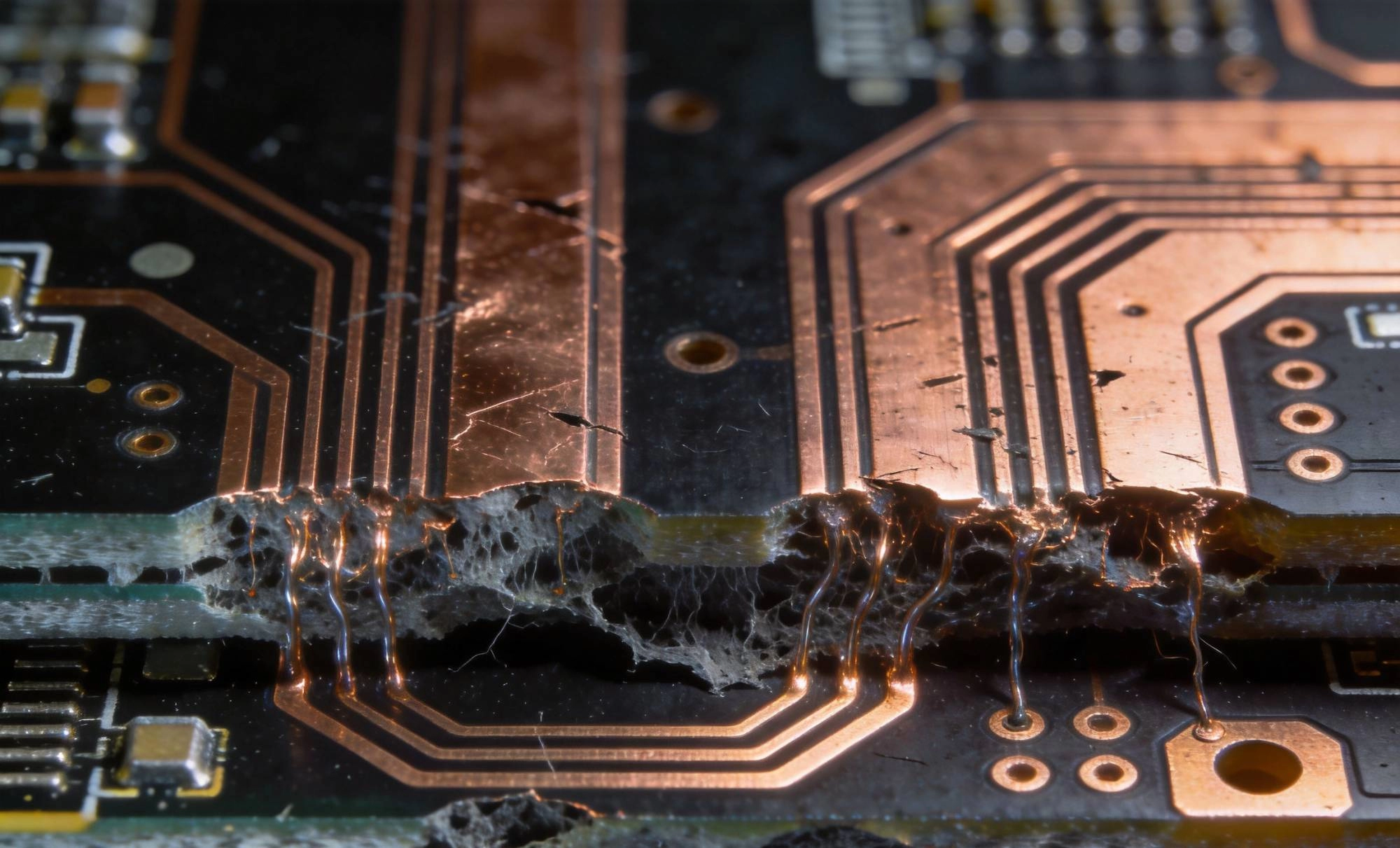
Conductive Anodic Filament is an electrochemical failure mechanism that occurs within PCB laminate materials. The process begins when copper ions migrate from anodic (positively biased) conductors through the Dielectric Material under specific conditions of moisture, temperature, and electrical stress. As copper ions travel through microscopic pathways within the laminate, they accumulate and form conductive filaments that bridge adjacent conductors.
The term describes both the process and its result: conductive filaments formed through anodic action. Unlike dendritic growth that occurs on surfaces, CAF filaments grow internally through the laminate matrix. This internal location makes CAF extremely difficult to detect during normal testing and inspection, as the filaments remain hidden between layers and within the Dielectric Material.
CAF formation requires a specific combination of factors that together enable the electrochemical migration process. Water molecules penetrating the laminate provide the electrolyte medium necessary for ion transport. Temperature gradients create conditions that drive water movement and accelerate electrochemical reactions. Electrical bias across the dielectric provides the electromotive force that drives copper ion migration.
Copper, being relatively active electrochemically, ionizes at the anode surface under bias stress. These copper ions then migrate through microscopic voids, cracks, or fiber pathways within the glass-reinforced laminate structure. The migration follows preferential paths along glass fiber bundles where the epoxy matrix may not fully penetrate or where thermal cycling has created micro-cracks.
CAF differs fundamentally from other common PCB failure modes. Surface dendritic growth, sometimes called whisker growth, occurs on exposed surfaces where ions can migrate in presence of moisture and bias. CAF occurs internally, requiring ion transport through the bulk laminate material rather than across surfaces.
CAF also differs from delamination in that it does not necessarily involve physical separation of layers. While delamination separates laminate layers visually and mechanically, CAF can exist within apparently intact laminate. A board passing visual inspection and even acoustic microscopy may still contain nascent CAF pathways invisible to conventional inspection methods.
CAF requires a specific conjunction of environmental and operational conditions. Understanding these conditions guides both design decisions and manufacturing process control. Risk assessment begins with evaluating which conditions exist in your target application and how severely each factor contributes to overall CAF susceptibility.
No single condition typically causes CAF alone. Rather, CAF emerges from combinations of factors that together create the electrochemical environment necessary for copper migration. Boards operating in benign conditions may never exhibit CAF despite other risk factors being present, while boards in harsh environments may fail rapidly when multiple accelerating factors combine.
Moisture serves as the critical catalyst for CAF formation, providing the ionic medium necessary for copper ion transport. Boards in high-humidity environments, outdoor applications, or products exposed to temperature cycling that causes condensation face elevated CAF risk. Even boards in controlled environments may absorb moisture during manufacturing, storage, or handling that later contributes to CAF during operation.
The mechanism involves water penetration into the laminate through microscopic pathways at via barrel walls, trace edges, and laminate imperfections. Once inside the laminate, water creates electrochemical cells between adjacent conductors. The amount of moisture required for CAF is surprisingly small, with even parts-per-million levels potentially contributing to ion transport over time.
Elevated temperatures accelerate the electrochemical reactions that drive CAF formation. The Arrhenius relationship means that reaction rates roughly double for every 10°C increase in temperature, making thermal conditions a critical factor in CAF kinetics. Boards operating continuously at elevated temperatures face higher CAF risk than those in controlled ambient conditions.
Thermal cycling compounds the temperature effect by creating mechanical stresses that open microscopic pathways within the laminate. Each thermal cycle stresses the copper-to-dielectric interface, potentially creating hairline cracks or separation at via barrels and trace edges. These thermally-induced pathways provide routes for water penetration and copper ion migration that would not exist in stable-temperature conditions.
CAF requires electrical bias to drive copper ion migration. The anodic conductor must be positively biased relative to the cathode, creating the electromotive force that transports ions. Higher voltage differences accelerate ion migration rates, though even low voltages can support CAF given sufficient time and other contributing factors.
Voltage gradient within the dielectric material influences CAF susceptibility. Fine-pitch high-density designs with small spacing between adjacent conductors create higher electric field strengths for a given voltage, potentially accelerating ion migration. The direction of bias also matters, as CAF preferentially forms along certain crystallographic orientations in the laminate structure.
Pcb Design decisions significantly influence CAF susceptibility independent of manufacturing quality or material selection. Designers who understand CAF mechanisms can make choices that reduce risk without necessarily requiring expensive materials or exotic manufacturing processes. These design principles should become standard practice for high-density boards where CAF risk exists.
Design for CAF resistance works alongside material selection and process control as part of a comprehensive reliability strategy. Even the best materials cannot fully compensate for designs that create excessive CAF risk through poor spacing, inadequate clearances, or problematic via configurations. Likewise, excellent design cannot overcome manufacturing defects that create entry points for moisture and ion transport.
Conductor spacing directly affects the distance copper ions must travel to form bridging filaments. Wider spacing increases the path length for ion migration, reducing the probability of filament formation over product lifetime. This relationship suggests that generous spacing improves reliability, though practical constraints limit how much spacing designers can afford in high-density applications.
Via-to-via spacing deserves particular attention in high-density designs. The barrel of a via presents a long straight copper surface that extends through multiple laminate layers. Adjacent via barrels create high-aspect-ratio pathways where ion migration can occur relatively unimpeded. Maintaining adequate spacing between adjacent via barrels reduces this risk substantially.
Thermal Vias, while essential for Heat Dissipation from components, create specific CAF vulnerabilities. The thermal via barrel passes through the complete board thickness, providing a direct pathway from one surface to another. Dense thermal via arrays under BGA packages create large numbers of parallel barrels that may suffer from manufacturing imperfections or thermal stress damage.
Reducing thermal via density where possible decreases the number of potential ion migration pathways. When dense thermal via arrays are necessary, consider using filled rather than open vias, which eliminates the hollow barrel that provides the ion migration channel. Filled Thermal Vias require additional manufacturing cost but provide substantially improved CAF resistance in thermally demanding applications.
Power plane geometries influence CAF risk through field distribution and voltage gradient effects. Sharp corners on power planes create localized high-field regions that may accelerate ion migration. Smooth, radiused geometries reduce field concentration and the associated CAF acceleration at plane edges.
Voltage differences between adjacent planes determine the driving force for ion transport through the inter-plane dielectric. Higher voltage differentials create stronger driving forces for migration. In high-voltage designs, consider whether all voltage differentials are necessary simultaneously or whether design modifications could reduce maximum voltage stress across vulnerable dielectric regions.
Laminate material properties significantly influence CAF susceptibility. Different resin systems, glass styles, and reinforcement architectures provide varying levels of resistance to ion transport and moisture penetration. Understanding material differences guides selection that improves reliability without requiring excessive design conservatism.
Material selection must balance CAF resistance against other requirements including electrical performance, Thermal Management, and cost. No single material optimizes all properties simultaneously. Trade-off analysis should weight CAF risk against other design requirements to identify materials that provide adequate CAF resistance while meeting overall product requirements.
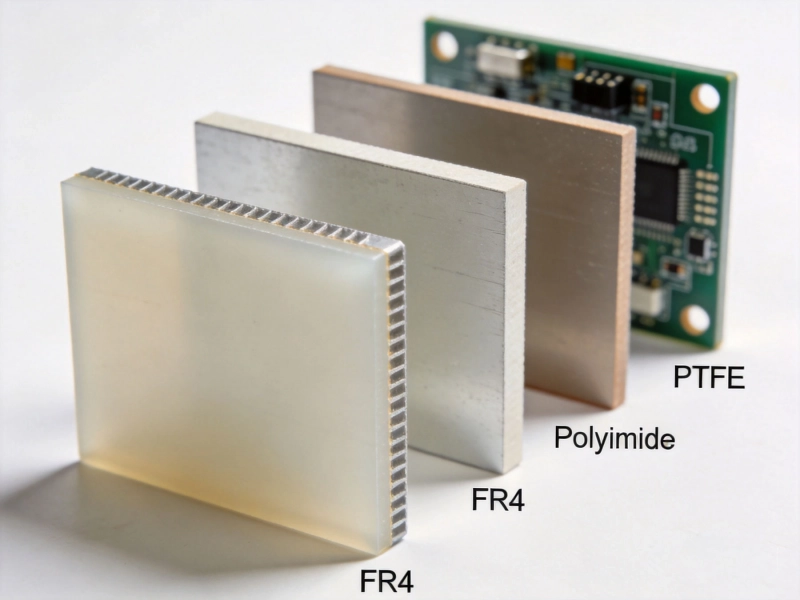
Different epoxy resin systems provide varying levels of CAF resistance. Standard FR-4 epoxy formulations, while economical and widely available, generally provide moderate CAF resistance. Higher-performance resin systems, including those specified for high-Tg or lead-free applications, often demonstrate improved CAF resistance due to better glass-fiber-resin interface properties.
Polyimide and multifunctional epoxy systems typically outperform standard FR-4 in CAF resistance testing. These materials achieve improved performance through better chemical bonding between resin and glass fibers, reducing the micro-voids that provide ion migration pathways. The premium pricing of these materials may be justified in applications where CAF reliability is critical.
The glass reinforcement style significantly influences CAF susceptibility. Standard weave styles with relatively open construction may not fully impregnate with resin, creating voids along glass fiber bundles. These voids provide pathways for moisture penetration and ion migration that accelerate CAF formation.
Low-spread weave styles with tighter glass fiber bundling reduce void formation and improve CAF resistance. Some manufacturers offer specially designed CAF-resistant glass styles that optimize the glass-resin interface for minimum ion transport. These specialty materials command premium pricing but provide measurably improved CAF resistance in critical applications.
Manufacturing process parameters affect CAF resistance even when using excellent materials. Incomplete resin cure leaves the laminate vulnerable to moisture absorption and ion transport. Improper lamination pressure can create voids or delaminations that provide pathways for CAF growth. Vendor process control significantly influences how well a given material performs in CAF testing.
Working with manufacturers who understand CAF mechanisms and control their processes accordingly provides benefits beyond material selection alone. Ask potential manufacturing partners about their CAF experience, testing capabilities, and process controls that address CAF risk. Manufacturers should be able to provide CAF test data for their standard processes when requested.
Manufacturing processes significantly influence CAF susceptibility through effects on laminate integrity, moisture content, and defect creation. Even designs optimized for CAF resistance can fail prematurely if manufacturing processes introduce vulnerabilities. Understanding which manufacturing factors matter helps evaluate potential manufacturing partners and troubleshoot reliability issues.
Manufacturing process control for CAF resistance focuses on three primary objectives: minimizing moisture introduction, ensuring complete lamination without voids, and preventing defects that create ion migration pathways. Each objective requires specific process controls and quality verification at appropriate manufacturing stages.
Moisture may be introduced during any manufacturing stage, from initial laminate storage through final assembly. Laminates and prepregs absorb moisture from ambient humidity if not properly stored. Assembly processes involving heat, including reflow soldering, can drive moisture deeper into the laminate if material moisture content was excessive entering the process.
Effective moisture control requires baking protocols before processes that involve elevated temperatures. Most laminate manufacturers specify maximum moisture content and baking requirements before reflow exposure. Following these specifications rigorously prevents moisture-related CAF acceleration during assembly. Your manufacturing partner should have documented moisture control procedures and should verify material condition before high-temperature processes.
Lamination process quality determines whether the finished board achieves the potential CAF resistance of the selected material. Incomplete lamination creates voids, delaminations, and poor glass-resin interface integrity. These manufacturing defects directly increase CAF susceptibility by providing pathways for ion transport that would not exist in properly laminated boards.
Quality verification includes acoustic microscopy inspection for delaminations and voids, cross-section analysis of sample boards, and scanning acoustic tomography for Hidden Defects. Manufacturers should perform these inspections routinely for boards intended for demanding applications. Request inspection data and process capability indices when qualifying manufacturing processes.
Vias represent high-risk features for CAF initiation due to the copper-dielectric interface extending through the complete board thickness. Manufacturing defects at via barrels, including cracks, voids in plating, and resin wicking, create entry points for moisture and ion migration. Via quality directly correlates with CAF susceptibility in high-density designs.
Via quality verification includes cross-section inspection, thermal stress testing, and resistance measurements. Thermal cycling tests that simulate field stress conditions reveal via weaknesses before boards reach customers. Manufacturers should perform these tests on qualification samples and periodically during production to verify process stability.
Detecting CAF in finished boards requires specialized testing that goes beyond standard quality verification. Standard electrical testing typically applies low voltages that may not reveal CAF pathways that become conductive only at higher stress levels. Understanding available test methods and their limitations helps establish appropriate qualification and production testing protocols.
No non-destructive testing method reliably detects all CAF conditions in finished boards. The filaments form gradually and may not create measurable resistance until they have progressed significantly. Testing protocols therefore focus on accelerating CAF formation to reveal susceptibility, rather than detecting existing filaments in every case.
Highly Accelerated Stress Testing uses elevated temperature and humidity conditions to accelerate CAF formation dramatically. Test chambers maintain conditions of 85°C and 85% relative humidity while applying electrical bias to test vehicles. Under these conditions, CAF that might require years to form in field conditions may appear within weeks or days.
HAST testing provides comparative data about CAF susceptibility of different designs, materials, or manufacturing processes. Boards failing HAST reveal CAF vulnerabilities that would likely cause field failures eventually. Passing HAST provides confidence, though it does not guarantee immunity from CAF under less stressful real-world conditions over extended timeframes.
Temperature Humidity Bias testing applies less aggressive stress than HAST, typically maintaining 85°C and 85% RH without pressure. This test requires longer duration but provides conditions more similar to actual field stress. THB testing remains a valuable qualification tool for boards expected to operate in humid environments.
THB test results depend heavily on test vehicle design and bias conditions. Simple test vehicles with aggressive spacing and bias may fail quickly even for adequate materials, while conservative test vehicles may pass even for marginal designs. Test vehicle design should reflect actual product conditions to provide meaningful qualification data.
When CAF failures occur, failure analysis confirms the failure mechanism and guides corrective action. CAF confirmation typically requires cross-sectioning through the failed area to expose internal filament structures. Optical microscopy and scanning electron microscopy reveal the characteristic copper filaments that confirm CAF rather than other failure mechanisms.
Failure analysis also examines contributing factors that enabled CAF growth, including laminate quality at the failure location, evidence of moisture entry, and any manufacturing defects. This root cause information guides design or process changes that prevent recurrence. Professional failure analysis services provide detailed reports with photomicrographs that document findings conclusively.
Several industry standards address CAF testing and qualification, providing reference methods and acceptance criteria. These standards help establish consistent testing protocols and enable comparison of results across different suppliers and testing laboratories. Understanding relevant standards guides appropriate test program development.
IPC standards provide widely recognized test methods for electronics manufacturing. IPC-TM-650 includes methods for CAF testing that define test vehicle design, stress conditions, and acceptance criteria. Other standards organizations, including IEC and JEDEC, publish related test methods that may be appropriate for specific applications.
IPC-TM-650 Method 2.6.25 provides the most widely referenced CAF test procedure. This method specifies test vehicle geometry, bias conditions, and accelerated stress testing requirements. Test vehicles include specific feature geometries that stress CAF susceptibility while remaining practical to manufacture and test.
Test interpretation follows defined resistance thresholds that indicate failure. Passing criteria typically require that no shorts develop between test features during the specified test duration. Results enable comparison of different material systems, designs, or manufacturing processes for CAF susceptibility.
Different industries and applications may specify additional or alternative CAF testing beyond standard methods. Automotive Electronics specifications typically require more aggressive testing reflecting demanding operating conditions. Aerospace and military specifications include CAF testing among environmental qualification requirements.
Consult application-specific standards when developing test protocols for regulated industries. Customer specifications may also include unique requirements that exceed standard methods. Early coordination with customers and regulators clarifies testing expectations before qualification programs begin.
Preventing CAF requires integrated attention to design, materials, and manufacturing throughout product development. No single action provides complete CAF protection; rather, prevention results from systematically addressing CAF risk factors at each development stage. Building CAF prevention into standard development practices costs less than troubleshooting CAF field failures.
The most effective prevention programs address CAF risk early in design, select appropriate materials and manufacturing partners, and verify effectiveness through appropriate testing. This systematic approach builds confidence that products will achieve target reliability without requiring excessive design conservatism or premium material costs.
Design practices that reduce CAF risk should become standard engineering discipline for high-density boards. Minimum spacing requirements, via density management, and thermal via consideration all belong in design rules for demanding applications. Design rule checks should flag features that create elevated CAF risk for engineering review.
Design optimization tools can help evaluate CAF risk during layout. Some EDA tools include CAF risk assessment features that estimate susceptibility based on spacing, voltage, and thermal conditions. While these estimates do not replace testing, they guide design iterations toward lower-risk configurations before releasing designs for manufacturing.
Material qualification should include CAF testing for demanding applications. Request CAF test data from laminate vendors for materials under consideration. Compare results across materials to identify those providing best CAF resistance within cost and performance constraints.
Vendor qualification should verify that manufacturing processes support CAF-resistant boards. Audit potential manufacturing partners for process controls related to moisture management, lamination quality, and via reliability. Request sample boards with aggressive test features that demonstrate CAF resistance under accelerated stress conditions.
CAF prevention requires ongoing attention as designs evolve and manufacturing processes change. Monitor field reliability data for signs of CAF-related failures. When failures occur, conduct thorough failure analysis to determine whether CAF contributed and whether design or process changes can prevent recurrence.
Periodically requalify materials and processes as formulations and capabilities evolve. Laminate manufacturers continuously improve products, and new options may provide better CAF resistance than materials qualified years ago. Staying current with material developments helps maintain competitive advantage in reliability performance.
Conductive Anodic Filament remains a significant reliability concern for high-density PCBs despite advances in materials and manufacturing processes. The electrochemical nature of CAF means that it cannot be completely eliminated, only managed to acceptable risk levels through careful attention to design, materials, and manufacturing controls.
Designing for CAF resistance reduces but does not eliminate risk. Material selection appropriate to application requirements provides a foundation for CAF performance. Manufacturing process control ensures that boards achieve the potential CAF resistance of selected materials. Testing verifies that designs, materials, and processes together provide acceptable reliability.
As Pcb Technology continues advancing toward higher densities and finer features, CAF management becomes increasingly important. The design practices and manufacturing controls appropriate for today's boards will require further evolution as tomorrow's technologies push density limits further. Staying current with CAF understanding protects product reliability as technology advances.
CAF (Conductive Anodic Filament) grows internally through the laminate material between conductors. Dendrite growth occurs on surfaces where ions migrate across exposed surfaces. CAF is generally more dangerous because it occurs within the board where inspection cannot easily detect it, while surface dendrites may be visible and removable before causing failures.
CAF cannot be completely prevented in all circumstances, but risk can be reduced to acceptable levels through design optimization, appropriate material selection, and manufacturing process control. For most applications, properly designed and manufactured boards achieve adequate CAF resistance for intended lifetime without field failures.
CAF formation time in field conditions depends on severity of contributing factors and ranges from months to years. Boards in benign indoor environments may never exhibit CAF despite risk factors present in design. Boards in hot, humid conditions with thermal cycling may fail within months. Accelerated testing compresses this timeline to days or weeks for qualification purposes.
CAF can form at relatively low voltages, though higher voltages accelerate the process. Many failures occur at typical operating voltages of 3.3V to 5V in consumer electronics. Higher voltages create stronger driving force for ion migration, increasing CAF probability. The electric field gradient matters more than absolute voltage.
CAF in finished boards is difficult to detect non-destructively. Standard electrical testing may not reveal CAF pathways until filaments are fully formed. Methods like thermal cycling with resistance monitoring, acoustic microscopy for voids, and cross-section analysis for failures provide indirect or destructive evidence of CAF susceptibility.
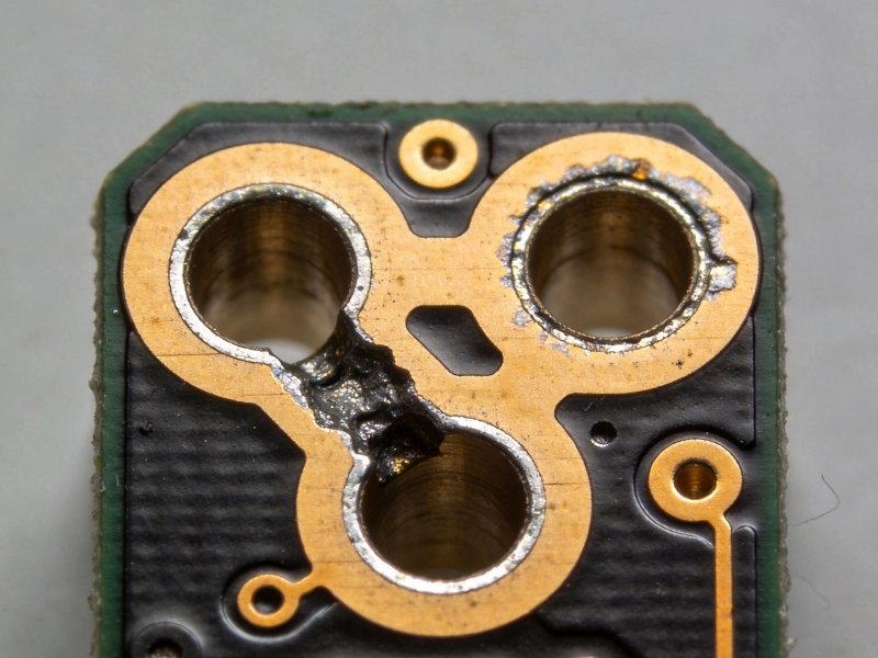
The Impact of Plating Voids on HDI Interconnect ReliabilityJuly/10/2026
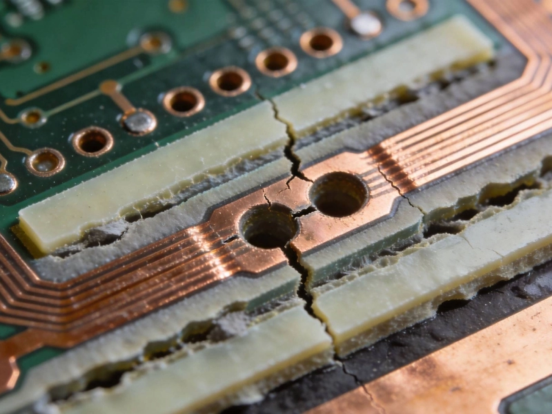
Understanding and Preventing Microvia Cracking in Thermal CyclingJune/12/2026

Enabling 5G Base Stations with Low-Loss HDI PCB MaterialsJune/27/2026

Implementing a Robust Quality Control System for HDI ManufacturingJune/15/2026

HDI PCBs in Industrial IoT (IIoT) and Smart Factory SensorsJune/29/2026

The Role of HDI in High-Speed Server and Data Center HardwareJuly/18/2026
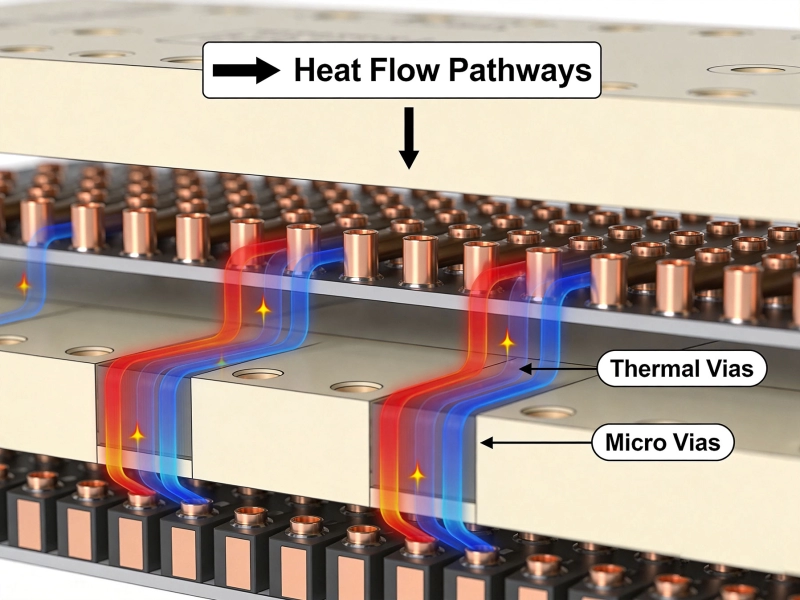
The Role of Thermal Vias in Dissipating Heat from HDI BoardsJune/09/2026
Selecting the Right Dielectric Materials for High-Performance HDI PCBsMay/28/2026