Open Nav

High-density Interconnect (HDI) substrates allow designers to pack more functionality into smaller areas by using fine lines, Microvias, Buried Vias, and high layer counts. As component density and power dissipation increase, Thermal Management becomes a primary constraint. Selecting high Thermal Conductivity materials for HDI substrates is no longer only a reliability consideration. It directly affects electrical performance, manufacturability, assembly yield, and long-term product lifetime.
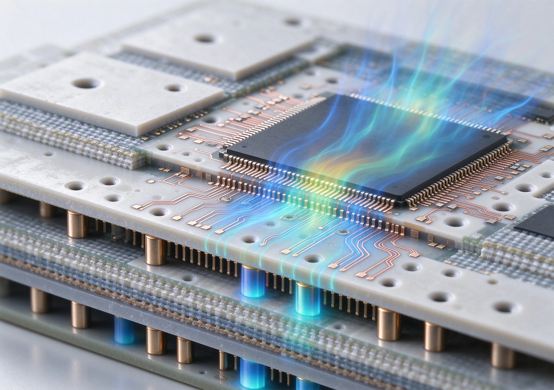
Standard FR-4 materials typically have low Thermal Conductivity, often in the range of 0.25–0.35 W/m·K. This is acceptable for many general-purpose boards, but HDI substrates used in high-power RF modules, advanced packaging, Automotive Electronics, Data Center Hardware, and compact power systems can generate localized hot spots that exceed the thermal capacity of conventional laminates.
Higher thermal conductivity helps move heat away from active devices, reduces temperature gradients across the board, and lowers the risk of via fatigue, solder joint failure, and dielectric degradation. In HDI structures, where Microvias and thin dielectric layers are common, material selection must balance Thermal Performance with electrical, mechanical, and process requirements.
Thermal conductivity alone does not determine whether a material is suitable for HDI substrates. Several interrelated properties must be evaluated together.
For high-speed digital and RF applications, dielectric constant (Dk) and dissipation factor (Df) are critical. Some thermally conductive materials improve heat transfer but introduce higher Dielectric Loss or less stable Dk at high frequency. The selected material should maintain acceptable Signal Integrity across the intended operating bandwidth.
High glass transition temperature (Tg) and decomposition temperature (Td) indicate better thermal stability during assembly and operation. Hdi Boards often undergo multiple reflow cycles, especially when combined with rigid-flex structures or advanced packaging. Materials with insufficient thermal stability may suffer from increased z-axis expansion, via barrel cracking, or delamination.
The coefficient of thermal expansion (CTE) must be compatible with copper, silicon dies, ceramic substrates, and other materials in the assembly. Mismatched CTE can cause mechanical stress during thermal cycling. For HDI substrates with fine-pitch microvias, low and stable CTE helps maintain interconnect reliability.
Moisture absorption affects dimensional stability, insulation resistance, and reflow performance. Materials with high moisture uptake may require stricter storage and baking controls. In Hdi Manufacturing, where thin dielectrics and small features are common, moisture-related defects can reduce yield.
HDI processing involves Laser Drilling, desmear, plating, and fine-line imaging. The substrate must maintain dimensional stability through these steps. Some high-thermal-conductivity fillers improve heat transfer but can reduce flexibility or increase brittleness, which may affect Laser Via formation and lamination quality.
Advanced FR-4 materials with higher Tg, lower Df, and improved Thermal Performance are often the first step up from standard laminates. They remain compatible with conventional PCB processes and offer reasonable cost efficiency. However, their thermal conductivity is still limited compared with specialized materials, so they are best suited for moderate power density HDI designs.
Polyimide materials provide high thermal stability, good mechanical toughness, and excellent performance under repeated thermal cycling. They are widely used in flexible and rigid-flex HDI substrates. Polyimide generally offers better high-temperature reliability than standard epoxy systems, but its thermal conductivity remains moderate unless specially formulated.
Bismaleimide triazine (BT) resin and Ajinomoto Build-up Film (ABF) materials are commonly used in IC substrates and advanced packaging. They support fine-line patterning, thin build-up layers, and reliable Microvia formation. Some grades offer improved thermal performance compared with conventional epoxy systems, making them suitable for high-density flip-chip and substrate-like PCB applications.
Ceramic-filled polymers combine organic processability with inorganic thermal fillers such as alumina, boron nitride, or silica. These materials can achieve significantly higher thermal conductivity than standard FR-4 while maintaining acceptable dielectric properties. They are often used in RF modules, power amplifiers, antennas, and thermally sensitive Hdi Applications.
Aluminum oxide (Al2O3), aluminum nitride (AlN), and silicon nitride (Si3N4) provide very high thermal conductivity and excellent dimensional stability. Ceramic substrates are suitable for extreme thermal environments, high-power RF circuits, and advanced power modules. However, they are more brittle, more expensive, and less compatible with standard HDI processes than organic laminates.
Metal-core PCBs, including aluminum-core and copper-core structures, provide excellent heat spreading through a metal base layer. They are widely used in LED modules, power converters, and motor control applications. For HDI designs, metal-core substrates can be combined with thin dielectric layers and fine-line circuitry, but via structures and insulation thickness must be carefully designed to maintain electrical isolation and process compatibility.
The first step is to define where heat is generated and how it should leave the system. If heat must travel vertically through the substrate, a high-conductivity dielectric or metal-core structure may be necessary. If heat spreads laterally through copper planes, thicker copper, Thermal Vias, and embedded heat spreaders may reduce the need for exotic materials.
For high-speed interfaces, RF circuits, and mmWave designs, Dk stability and low loss are often more restrictive than thermal conductivity. A material with excellent thermal performance but poor high-frequency behavior can degrade Insertion Loss, Impedance Control, and phase consistency.
HDI substrates rely on laser-drilled microvias, stacked or staggered via structures, and thin dielectric layers. The selected material must support reliable laser ablation, desmear, and Copper Plating. Some ceramic-rich laminates are more difficult to laser drill or may require specialized process parameters.
Materials must survive lead-free reflow, possible multiple assembly passes, and any required rework steps. High thermal mass substrates may require adjusted reflow profiles because they absorb and distribute heat differently than thin FR-4 boards.
Automotive, industrial, aerospace, and medical applications often require extended thermal cycling, humidity resistance, and long-term material stability. In these cases, CTE matching, moisture absorption, and interconnect fatigue performance should be evaluated alongside thermal conductivity.
High-performance materials usually carry higher cost and longer lead times. For high-volume products, total cost of ownership should include not only material price but also yield impact, testing requirements, assembly complexity, and field failure risk.
Material selection works best when combined with thoughtful HDI design.
In HDI substrates, thermal vias must be designed carefully because Microvia diameter, fill material, and plating thickness affect both electrical connectivity and heat transfer. Copper-filled vias generally provide better thermal conduction than non-filled vias, but they also increase process complexity.
High thermal conductivity materials may require adjustments in lamination pressure, drilling parameters, desmear chemistry, and surface preparation. Ceramic-filled laminates can be more abrasive to drill bits. Metal-core substrates require controlled insulation thickness to prevent breakdown. Thin build-up films used in HDI structures must maintain uniformity after lamination to avoid impedance variation.
Early engagement with the substrate manufacturer is important. Material datasheets provide baseline values, but actual performance depends on stackup, copper distribution, via density, and processing conditions. Requesting process capability information before finalizing the design can prevent costly revisions.
Selecting high thermal conductivity materials for HDI substrates requires a system-level view. Thermal conductivity is essential, but it must be balanced with dielectric performance, CTE, Tg, moisture resistance, microvia compatibility, assembly requirements, and cost. For moderate thermal loads, advanced FR-4 or polyimide materials may be sufficient. For higher power density or advanced packaging, ceramic-filled laminates, BT/ABF systems, metal-core structures, or ceramic substrates may provide better results.
The most reliable HDI designs combine appropriate material selection with thermal-aware layout, validated via structures, and early collaboration with manufacturing partners. When Thermal Management is addressed at the material and design stages rather than after prototype failure, product performance, yield, and long-term reliability improve significantly.
Standard FR-4 is typically around 0.25–0.35 W/m·K. Advanced laminates may reach 1–3 W/m·K, while ceramic-filled materials and ceramics can exceed these values significantly. The required level depends on power density, board thickness, and cooling strategy.
Yes, but the design must account for insulation thickness, via structures, and manufacturing constraints. Metal-core HDI is more complex than standard HDI, so early feasibility review with the manufacturer is recommended.
Not automatically. If the material has poor CTE matching, high moisture absorption, or unsuitable dielectric properties, reliability may not improve. Thermal performance should be evaluated together with electrical and mechanical behavior.
Typical applications include RF modules, power amplifiers, automotive ECUs, LED systems, Data Center Hardware, advanced IC substrates, and compact power converters where heat density and board size are tightly constrained.
What is High Density Interconnect (HDI) PCB?May/28/2026
Essential HDI PCB Design Rules for Beginners and ExpertsMay/28/2026
FR-4 vs. High-Tg Materials: What Works Best for HDI Applications?July/07/2026
Understanding the Role of Copper Foil Roughness in Signal IntegritySeptember/23/2026
An Introduction to ABF (Ajinomoto Build-up Film) for Advanced HDIJuly/27/2026
Why Low Loss Materials are Critical for High-Speed HDI DesignsSeptember/01/2026
Thermal Conductivity in HDI Materials: A Guide for EngineersOctober/27/2026
Selecting the Right Dielectric Materials for High-Performance HDI PCBsJune/05/2026