
In orbit, 35,786 kilometers above the equator, a communications satellite operates in an environment that is almost perfectly hostile to electronics. It is bombarded by radiation from solar flares and cosmic rays, subjected to extreme thermal cycling as it moves between direct sunlight and the cold of the Earth's shadow, and expected to operate continuously for 15 to 20 years without any possibility of repair. Every component on its printed circuit boards must be chosen, assembled, and qualified with this reality in mind.
Interconnects — the connectors, solder joints, vias, and contact systems that carry signals and power between circuits — are among the most critical and most failure-prone elements in satellite PCB assemblies. A connector that leaks in vacuum, a solder joint that cracks under thermal cycling, or a via that fails after radiation exposure can end a mission. Designing and building interconnects for space is not an exercise in applying extra safety margins to terrestrial designs. It requires a fundamentally different engineering approach at every stage of the process.
Understanding why space-grade interconnects require such specialized treatment begins with understanding what is happening up there. A satellite in geostationary orbit experiences a set of environmental stresses that are qualitatively different from anything encountered in terrestrial or even high-reliability industrial applications.
Space radiation comes from three principal sources: trapped protons and electrons in the Van Allen belts, solar particle events (large eruptions from the sun that release intense bursts of high-energy particles), and galactic cosmic rays from outside the solar system. Each of these sources poses distinct challenges for electronic interconnects.
Total Ionizing Dose (TID) accumulates over time and degrades the performance of semiconductor devices, changes the properties of dielectric materials in PCB laminates, and causes gradual increase in leakage current in insulators. For interconnects specifically, TID can cause discoloration and degradation of polymeric materials used in connector housings and cable insulation, increased outgassing from organic materials, and gradual changes in the mechanical properties of solders and plating.
Single Event Effects (SEE) — upsets, latchups, and burnout events caused by individual high-energy particles — are less relevant to passive interconnect structures but can affect active components that drive interconnect circuits. Displacement damage from high-energy neutron and proton bombardment degrades the crystal lattice of semiconductor materials over time, contributing to long-term reliability concerns.
For space-grade PCB interconnects, radiation-tolerant materials are selected explicitly: polyimide and quartz-polyimide laminates rather than standard FR-4, which is susceptible to TID-induced degradation; gold plating rather than tin or nickel-palladium finishes, which can form intermetallic compounds under radiation; and tight controls on organic content to minimize outgassing under vacuum.
A geostationary satellite experiences approximately 2,700 thermal cycles per year — each one a swing from approximately minus 65°C to plus 125°C as the satellite moves in and out of the Earth's shadow. These cycles occur in vacuum, where there is no air to conduct heat and no convective cooling. The only heat transfer mechanism is radiation, which is slow and creates large thermal gradients within the spacecraft structure.
These conditions affect interconnects in several critical ways. Thermal expansion mismatch between dissimilar materials — a ceramic chip capacitor and an FR-4 board, or a gold-plated Kovar connector shell and an aluminum chassis — creates cyclic stress at every temperature transition. Over thousands of cycles, this stress causes fatigue in solder joints, wire bonds, and mechanical contact systems. In vacuum, there is no moisture to contribute to corrosion, but the absence of moisture also eliminates self-healing corrosion mechanisms that operate in humid air.
More critically, vacuum causes evaporation of organic materials — a phenomenon called outgassing. Polymers, adhesives, conformal coatings, and even some epoxy potting compounds release volatile compounds that can condense on optical surfaces, thermal radiators, and solar cell arrays. This is why space-grade interconnects use exclusively low-outgassing materials rated per ASTM E595 — materials that lose less than 1% of their mass by total mass loss (TML) and less than 0.1% of collected volatile condensable materials (CVCM).
Satellites experience intense vibration loads during launch — from rocket engine ignition, staging events, and acoustic pressure waves reverberating inside the payload fairing. Typical launch vibration levels for geostationary satellites are in the range of 5–30g RMS across a frequency spectrum extending to 2000 Hz, with transient shock events reaching 100g or higher.
Interconnects must survive these loads without experiencing contact resistance changes, solder joint fractures, or connector decoupling. For board-to-board connectors, this means specifying connectors with positive latching mechanisms, using staked or potted connector bodies to prevent movement under vibration, and designing board support structures that limit the amplitude of board flex under load.
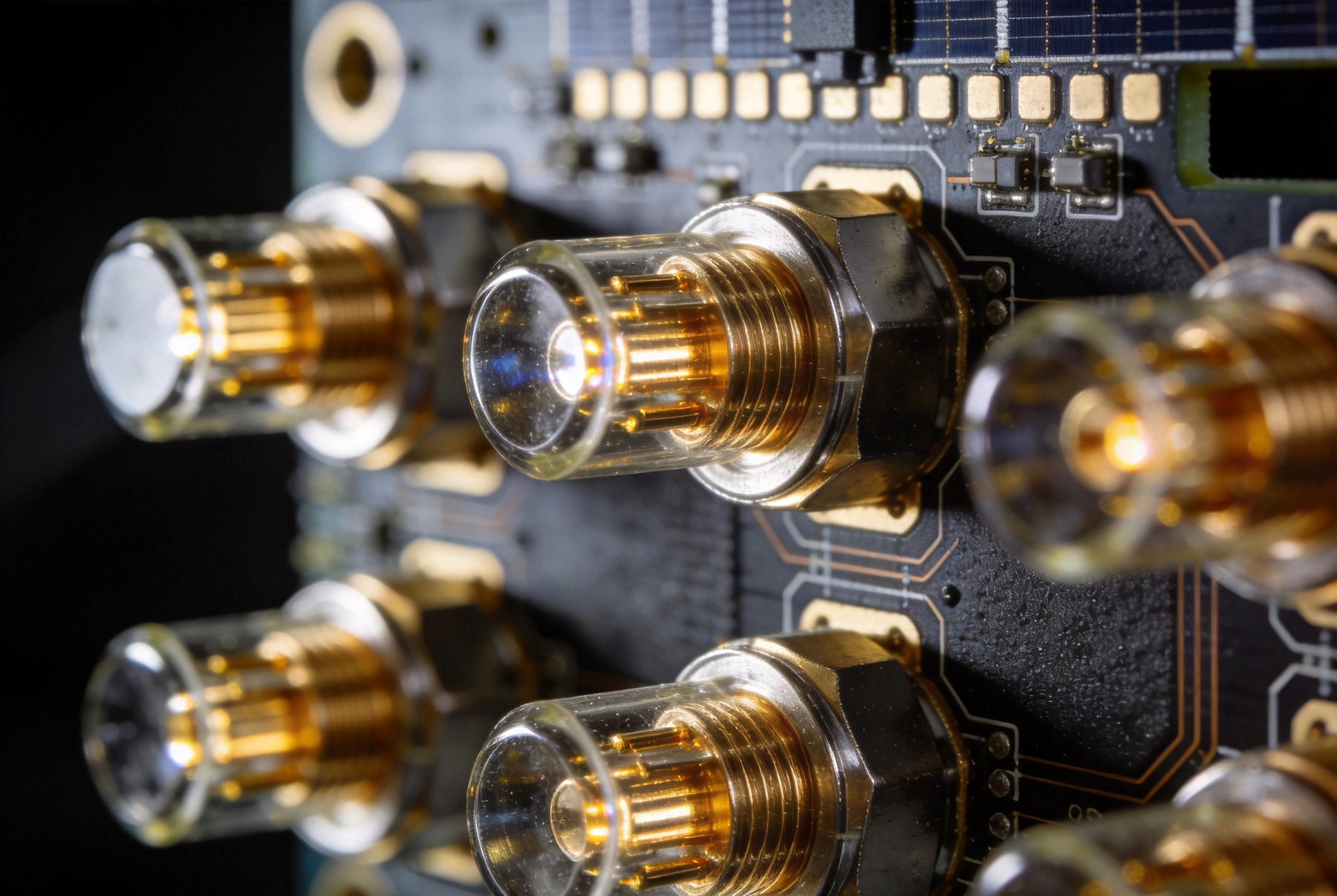
Hermetic connectors provide a sealed feedthrough through the chassis wall, maintaining the internal pressure and atmospheric composition of the spacecraft while connecting to external cables or antennas. These connectors must maintain their seal through launch vibration, thermal cycling, and radiation exposure over the mission lifetime.
Hermetic connectors for space applications are specified to meet MIL-PRF-39012 (for coaxial versions) and MIL-DTL-83513 (for rectangular micro-D connectors) or equivalent European and Japanese standards. Key requirements include helium leak rates below 1×10⁻⁸ atm·cc/sec, contact resistance stability under thermal cycling, and materials compatible with the outgassing requirements of ASTM E595.
The contacts inside hermetic feedthroughs are typically gold-plated to prevent corrosion and maintain low contact resistance. Contact materials are selected for hardness and resistance to galling — the tendency of two gold surfaces to cold-weld under pressure. A thin underplate of nickel or palladium prevents gold migration into the contact spring mechanism.
Within the satellite electronics stack, board-level interconnects use increasingly miniaturized connector families to save mass and board area. Micro-D connectors (MIL-DTL-83513) offer up to 100 contacts in a form factor approximately 30% smaller than standard D-Sub connectors. Nano connectors (MIL-DTL-32139) push this further, with contact densities up to 160 in packages sized for high-densityPayload modules.
These connector families are available in space-qualified versions with radiation-tolerant materials, low-outgassing housings, and extended temperature ranges. Gold-plated contacts are standard. Many are qualified to the NASA EEE-INST-002 guidelines, which provide comprehensive selection and screening requirements for electrical, electronic, and electromechanical components used in NASA space missions.
For some high-reliability space applications, solder-based interconnects are being supplemented or replaced by press-fit technology — where compliant pins are inserted into plated through-holes with controlled interference fit, creating a gas-tight connection without solder. Press-fit interconnects offer advantages in terms of inspection simplicity, rework capability, and resistance to vibration-induced fatigue, though they require tighter tolerance control on the plated through-holes.
Spring contact systems — using individually compliant spring fingers rather than rigid pins — are increasingly used for test interconnects and for applications where thermal expansion mismatch between components and boards creates unacceptable stress on solder joints. These systems absorb thermal cycling displacement without generating fatigue damage, making them particularly suited to the extreme thermal ranges of space applications.
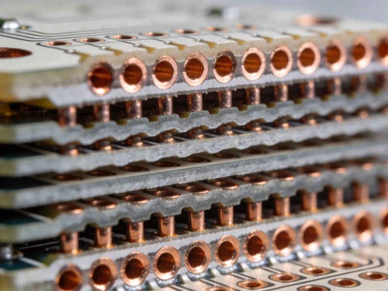
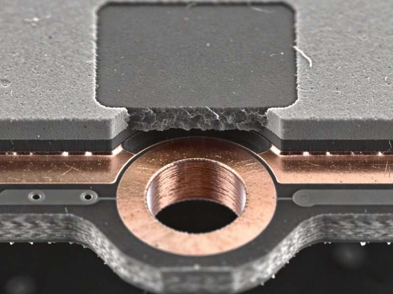
Plated through-holes (PTHs) and blind/Buried Vias are among the most vulnerable features in multilayer space PCBs. Thermal cycling causes differential expansion between the Copper Plating inside the via barrel and the PCB laminate, creating cyclic stress at the barrel-to-pad interface. Over thousands of thermal cycles, this stress can cause barrel cracks — micro-fractures in the plated copper that result in intermittent or complete open circuits.
Via reliability engineering for space applications addresses this through several design and manufacturing techniques:
Modern communication satellites operate at data rates of multiple gigabits per second, particularly in digital beamforming and high-throughput payload architectures. At these frequencies, the interconnect — whether a trace on a PCB, a via, or a board-to-board connector — must maintain controlled impedance within tight tolerances to prevent signal reflection, distortion, and data corruption.
Space-grade controlled impedance design requires careful attention to the dielectric constant and dissipation factor of the laminate material across the operating temperature range. Polyimide and quartz-polyimide materials offer more stable dielectric properties across temperature than standard FR-4. Full-stackup simulation using electromagnetic solvers (HFSS, CST, Sigrity) is standard practice for validating impedance continuity through vias and connectors at frequencies above 1 GHz.
The PCB laminate material for space applications must satisfy several competing requirements: radiation tolerance (for TID resistance), thermal stability across the operating temperature range, low outgassing (ASTM E595 compliance), stable electrical properties, and adequate mechanical strength to survive launch vibration.
The most commonly used space-grade laminates include:
Solder alloy selection for space interconnects prioritizes thermal fatigue resistance above all other properties, because the primary failure mode is fatigue damage from thermal cycling. Tin-lead (Sn63Pb37) solders offer superior thermal fatigue resistance compared to most lead-free alternatives and remain the preferred choice for many space-grade assemblies despite RoHS and environmental regulations. Where lead-free is required, SAC305 (Sn96.5Ag3Cu0.5) with small additions of nickel or other dopants offers improved thermal fatigue performance compared to standard SAC alloys.
For high-reliability space applications, the trend is toward specialty high-reliability solders with controlled impurity levels: low oxygen content, controlled particle size distribution for solder paste, and stringent limits on elements like gold (which forms brittle intermetallic compounds with tin). Supplier qualification and lot-to-lot consistency are critical requirements for space-grade solder procurement.
Space-grade solder joint acceptance criteria are defined by IPC-A-610 Class 3 (High Reliability Electronics) as a baseline, with additional requirements from customer-specific standards (ESA, NASA, Boeing, Airbus, etc.) layered on top. For Class 3 assemblies, key solder joint requirements include:
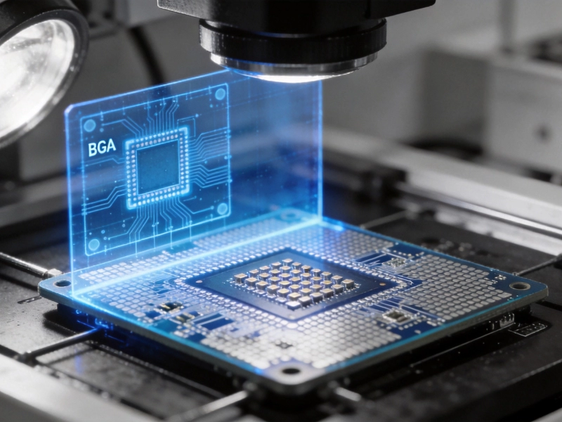
For the most critical interconnects, X-ray Inspection of every joint — not just statistical sampling — is specified to verify internal joint integrity for BGAs, QFNs, and other packages with hidden solder joints.
Space-grade interconnect systems must be qualified through a combination of design validation testing, lot qualification testing, and ongoing screening during production. The specific requirements vary by mission profile and customer, but common elements include:
For space applications, loose particles inside sealed enclosures represent a catastrophic risk — a particle that shifts under vibration and shorts two circuits can cause a mission failure. Particle Impact Noise Detection (PIND) testing per MIL-STD-883 Method 2020 subjects sealed components to a sequence of vibration, acoustic, and thermal steps to dislodge any loose particles and detect their impact noise. Any component that produces detectable particle noise is rejected.
PIND testing is required for all sealed connector bodies and any other hermetically sealed enclosure used in space applications. It is one of the most demanding and unique aspects of space-grade interconnect qualification that has no parallel in terrestrial or even aerospace-grade (non-space) applications.
Beyond qualification, individual components and boards undergo screening — inspection and testing applied to each production unit to catch defects that may have been introduced during manufacturing. Standard space-grade screening flows include:
Derating requirements — applying components below their maximum rated stress — are specified in standards like NASA Goddard Space Flight Center's EEE-INST-002 and the MIL-HDBK-1547 component derating guidelines. For interconnects, this means specifying connector current ratings at no more than 50% of their tested maximum, and specifying solder joint thermal and mechanical limits conservatively.
China has invested significantly in space Electronics Manufacturing capability over the past two decades, driven by the rapid expansion of its domestic space program and the growth of commercial space. Several Chinese manufacturers now hold space-grade manufacturing certifications and have delivered flight hardware for Chinese space missions, LEO satellite constellations, and commercial satellite programs.
The key certifications to look for when evaluating a Chinese manufacturer for space-grade interconnect work include:
The space-grade component supply chain for interconnects is heavily concentrated in the United States, Europe, and Japan. Specialty connectors, radiation-tolerant laminates, and high-reliability solder materials often require import to China, with associated logistics complexity, duty costs, and lead time considerations. Evaluating a manufacturer's ability to manage this supply chain — including import licensing, supplier qualification, and incoming inspection — is an important part of assessing their readiness for space-grade work.
For commercial LEO constellations — where volumes are higher and cost pressure is greater than for traditional geostationary satellites — there is increasing interest in using COTS (Commercial Off-The-Shelf) components with extended screening rather than full space-grade versions. This approach trades some reliability margin for significantly lower cost and faster availability, and it requires careful analysis of the radiation environment and mission lifetime to confirm that the risk is acceptable.
High-reliability interconnects for satellite and space communication represent the intersection of extreme engineering requirements and uncompromising manufacturing discipline. The space environment — radiation, thermal cycling, vacuum, vibration — imposes demands on connector selection, Pcb Design, material specification, and assembly process that go well beyond any terrestrial application. Meeting these demands requires engineering expertise, specialized manufacturing capability, rigorous qualification and screening, and a supply chain built around reliability rather than cost alone.
For satellite programs — whether traditional geostationary missions or commercial LEO constellations — the interconnect is not a commodity. The connector, the solder joint, the via, and the laminate all carry mission-critical responsibility. Investing the engineering effort to select, design, and build them correctly is not optional — it is the cost of doing business in space.
In the vacuum of space, organic materials release volatile compounds that can condense on critical surfaces — optical lenses, thermal radiators, solar cells, and sensors — degrading their performance permanently. Materials used in or near interconnects (connector housings, cable insulation, conformal coatings, potting compounds) must meet ASTM E595 requirements with Total Mass Loss below 1% and Collected Volatile Condensable Materials below 0.1%. This effectively eliminates most standard commercial materials and requires space-qualified, low-outgassing alternatives for all organic components in the interconnect system.
Space-grade satellite PCBs use polyimide, quartz-polyimide, BT resin (Bismaleimide-Triazine), or in some cases LTCC (Low-Temperature Co-Fired Ceramic) for the most demanding applications. These materials offer superior radiation tolerance, thermal stability, and outgassing performance compared to standard FR-4, which is susceptible to total ionizing dose degradation and excessive outgassing. The specific material choice depends on the trade-off between performance requirements, radiation environment, and program cost constraints.
Total Ionizing Dose (TID) accumulates over the mission lifetime and degrades polymeric materials, increases leakage current in dielectric materials, and changes the mechanical properties of solders and plating. For interconnects, TID primarily affects organic connector housings, cable insulation, and conformal coatings, which can become brittle or discolored over time. Single Event Effects (SEE) from individual high-energy particles are more relevant to active components than to passive interconnects. Space-qualified interconnect systems use radiation-tolerant material selections — gold plating instead of tin, polyimide rather than FR-4, and radiation-screened component grades — to ensure reliable operation through the mission lifetime.
Particle Impact Noise Detection (PIND) testing per MIL-STD-883 Method 2020 is required for all sealed electronic enclosures used in space applications. The test subjects sealed components to sequential vibration, acoustic excitation, and thermal shock steps to dislodge any loose particles inside the enclosure. Sensitive accelerometers detect the impact noise of any particles. A component that produces detectable particle noise is rejected because a loose particle inside a sealed connector could shift under launch vibration and cause a short circuit — a potentially catastrophic failure in a space system with no repair capability.
Space-qualified interconnects are designed and tested specifically for the orbital and deep-space environment, including vacuum operation, radiation exposure, and long-duration thermal cycling over 15–20 year mission lifetimes. Aerospace-grade (avionics) interconnects are designed for aircraft environments, which include humidity, pressure variation, and vibration but not the vacuum, radiation, and extreme thermal cycling of space. Space qualification requirements — including PIND testing, outgassing certification, particle radiation screening, and extended thermal cycling — are substantially more demanding and specific than standard aerospace requirements.
Commercial Off-The-Shelf (COTS) components can be used in satellite applications when the mission profile and radiation environment allow. Commercial LEO constellation programs often use COTS components with extended screening to reduce cost and improve availability, accepting some reduction in reliability margin in exchange. For geostationary missions with 15+ year lifetimes, full space-qualified components are typically required. The key is to perform a rigorous radiation analysis for the specific orbit, model the total ionizing dose over the mission lifetime, and select components with demonstrated margin above the expected dose. COTS components without this analysis carry unknown risk that may not be acceptable for critical missions.
HDI PCB Requirements for Mission-Critical Aerospace ApplicationsJune/30/2026
Designing HDI Boards to Withstand Extreme Aerospace EnvironmentsJuly/22/2026
Challenges of Integrating HDI in High-Efficiency Power InvertersJuly/16/2026

Mastering Stack-up Design for Optimal HDI PerformanceJune/08/2026
The Art of Microvia Placement: Staggered vs. Stacked ViasSeptember/24/2026
Reliability Challenges of Via-in-Pad Plating Filled (VIPPO) TechnologySeptember/30/2026

How HDI Technology Supports Advanced Driver Assistance Systems (ADAS)June/25/2026
How X-Ray Inspection (AXI) Detects Hidden Defects in HDI BoardsJuly/30/2026